
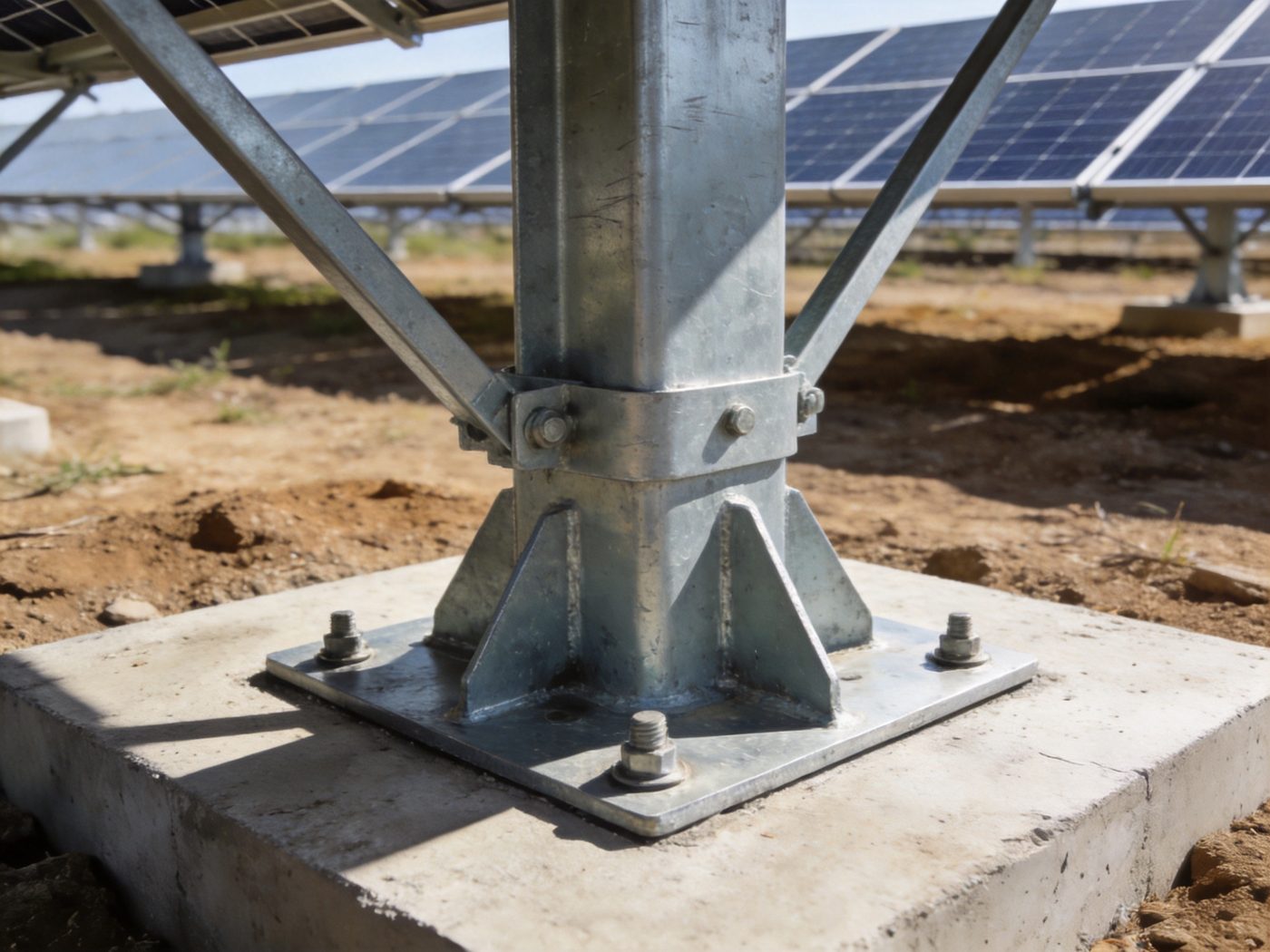
Understanding load transfer principles is fundamental to designing reliable solar foundation systems — the structural performance of every foundation type, from driven steel piles to grouted rock anchors, is governed not by the foundation element itself but by the mechanism through which forces generated in the solar mounting system above are transmitted into the soil or rock mass below. Whether using pile, screw, concrete, or rock anchoring solutions, structural stability depends on how loads are transferred to the soil or rock mass through one or more of four fundamental resistance mechanisms: end bearing, skin friction, dead weight counterbalance, or grout/mechanical bond — and on whether the soil or rock at the resistance interface has sufficient strength and stiffness to sustain the transferred load without failure or excessive deformation over the 25–50-year project life. For a complete overview of all solar foundation types and how each mobilizes these resistance mechanisms in different soil and geological conditions, visit our Solar Foundation Systems Guide.
Load transfer design is where the abstract concept of “foundation capacity” is converted into measurable engineering quantities: the end bearing stress at a pile tip, the skin friction distribution along a screw shaft, the net uplift resistance of a concrete footing under wind loading, or the grout-rock bond stress in a drilled anchor. Each of these quantities can be calculated from established geotechnical theory and site-specific soil data — and each governs a different failure mode that must be checked with the appropriate safety factor before a foundation design can be certified as structurally adequate. The precision of load transfer calculations is the primary engineering differentiator between a solar foundation design that performs reliably for 30 years and one that requires remediation after the first extreme wind season.
Technical Snapshot: Load Transfer Design Parameters for Solar Foundation Engineering
| Parameter | Description / Typical Range | Governing Failure Mode | Engineering Note |
|---|---|---|---|
| Axial Compression Load (Pc) | Dead load: 2–8 kN/foundation (module + racking + hardware weight); Snow load: 0.5–5 kN/foundation (climate-dependent); Equipment load: 0.5–3 kN during construction; Net compression = Pdead + Psnow + Pequipment | Bearing capacity failure under footing base; pile end bearing overstress; excessive consolidation settlement in clay | Axial compression typically does not govern foundation design in solar mounting — the dead load is low relative to the foundation capacity mobilized for wind uplift resistance; the exception is large-format bifacial module installations with heavy aluminum frame racking where dead load per foundation position can reach 12–18 kN, approaching the governing load in weak clay soil |
| Net Wind Uplift Force (Tu) | Tu = (Cn,uplift × qz × Atributary) − 0.9 × Pdead; typical range: 8–45 kN per foundation at perimeter positions; interior positions: 4–20 kN; corner positions: 15–60 kN in high-wind zones (V ≥ 140 mph / 63 m/s) | Tension failure in pile skin friction; screw helix bearing failure in uplift; concrete footing overturning or net uplift exceeding dead weight; rock anchor grout-bond failure | Net uplift Tu governs foundation design at all perimeter and corner positions in standard solar arrays — the governing LRFD load combination is 0.9D + 1.0W per ASCE 7-22 Table 2.3.1 Combination 7, which minimizes the dead load credit (0.9 factor) while applying full wind force; this combination produces larger net Tu than wind alone because it simultaneously reduces the favorable dead weight resistance |
| Lateral Wind Force (Hw) | Hw = CD × qz × Aprojected; typical range: 3–18 kN per foundation; tracker systems in stow position (panels vertical) experience maximum lateral force; fixed-tilt arrays: lateral force proportional to sin(tilt angle) × projected area | Lateral foundation displacement exceeding tracker drive tolerance (±10–15 mm); pile or screw bending overstress at ground surface; footing sliding on base; column-to-foundation connection shear failure | Lateral force governs pile and screw bending moment design at the ground surface — the maximum bending moment in a laterally loaded pile occurs at 0.3–0.8 m below ground surface (depth of fixity), not at the ground surface; pile section modulus must be checked at the depth of fixity, which requires a p-y curve lateral analysis or simplified Broms method calculation, not just the surface moment from Hw × eccentricity |
| Overturning Moment (MOT) | MOT = Hw × heff + Tu × eeccentricity; heff = effective height from foundation bearing level to centroid of wind force on panel; typical heff = 1.5–3.5 m for fixed tilt; 2.5–5.0 m for tracker in stow position | Footing tipping/overturning when MOT/Tu,uplift > B/2 (eccentricity exceeds kern limit); pile or screw maximum bending moment overstress; rock anchor bearing plate edge crushing on rock surface | Overturning moment produces differential axial loading on the two anchor bolts of a two-bolt column base: one bolt in tension (uplift side), one in compression (compression side); the tension bolt demand = Tu,direct + MOT/s where s = bolt spacing; this combined tension from direct uplift + overturning must be checked against the anchor bolt tensile capacity — overturning moment typically increases governing bolt tension by 25–60% relative to direct uplift alone |
| End Bearing Capacity (Qb) | Clay (undrained): Qb = Atip × 9 × su; Sand (drained): Qb = Atip × σ’v × Nq; Nq = 10–80 depending on φ’ (Meyerhof); typical Qb = 15–120 kN for 76 mm pile tip in medium-dense sand | Pile tip punching into soft layer below assumed bearing stratum; premature pile refusal on dense sand above target depth; screw helix pull-through in soft clay under uplift | End bearing in clay is rate-dependent — Qb calculated from undrained su (short-term, construction period) is higher than long-term drained capacity; for permanent solar foundations, long-term bearing capacity must be checked using drained parameters (c’, φ’) even if undrained capacity appears adequate at installation |
| Skin Friction Capacity (Qs) | Clay (α method): Qs = Σ(α × su × Ashaft); α = 0.5–0.9; Sand (β method): Qs = Σ(Ks × σ’v × tan δ × Ashaft); Ks = 0.7–1.5; typical Qs = 25–180 kN for 1.5 m pile in medium clay or dense sand | Progressive skin friction failure (pile settlement as friction is mobilized incrementally); tensile skin friction reduction under uplift (60–80% of compression value in sand) | Skin friction in tension (uplift loading) is consistently lower than skin friction in compression — the reduction factor is 0.6–0.8 for sand (Poisson contraction reduces radial effective stress on shaft under tension) and 0.7–0.9 for clay; this reduction must be applied when checking pile or screw uplift capacity from skin friction — using compression-based skin friction for uplift capacity check is unconservative and a common design error |
| Torque-to-Capacity Correlation (Kt) | Kt = 30–65 m⁻¹ for standard 76 mm tube shaft screws in cohesive soil; Kt = 40–75 m⁻¹ in cohesionless soil; Qallow = Kt × Tinstall (Tinstall = installation torque, kN·m); typical Qallow = 40–200 kN for Tinstall = 1.0–3.5 kN·m | Over-reliance on Kt correlation without verification testing; Kt variability in heterogeneous soil; helix distortion at high torque reducing bearing area | Kt is an empirical correlation with ±30–40% variability in non-uniform soil — it is a real-time installation acceptance criterion, not a substitute for structural capacity calculation; the design capacity from torque must be confirmed consistent with the calculated capacity from bearing area × unit bearing pressure for the soil at helix depth; discrepancy > 25% between torque-based and bearing-area-based capacity requires investigation before acceptance |
| Grout-Rock Bond Stress (τbond) | Hard rock (UCS > 100 MPa): τbond = 1.4–3.5 MPa; Medium rock (UCS 25–100 MPa): τbond = 0.7–2.0 MPa; Weak rock (UCS 5–25 MPa): τbond = 0.35–0.8 MPa (per FHWA NHI-99-015); Required bond length Lbond = Tu/(π × dhole × τbond,allow) | Grout-rock interface shear failure; rock cone pullout; anchor rod steel tensile rupture (in that failure sequence) | τbond is the most site-variable structural parameter in rock anchor design — the same rock type can exhibit 2–4× variation in τbond depending on drill hole surface roughness, borehole cleanliness, groundwater presence during grouting, and joint spacing; pre-production pull-out testing is the only reliable method to confirm site-specific τbond before committing to production anchor installation across the full project |
Types of Loads Acting on Solar Foundations
Axial Compression Loads: Dead Load, Snow Load, and Construction Load
Axial compression loads act vertically downward on solar foundations and are resisted by bearing pressure at the foundation base or by shaft friction in compression — the same mechanisms that govern building column foundations. In solar mounting, axial compression originates from three sources: (1) Permanent dead load: the combined weight of solar modules (typically 11–18 kg/m²), mounting rails, clamps, connection hardware, and the foundation element itself; for a standard 2-landscape-module-wide fixed-tilt row with 72-cell modules at 1.8 m × 1.0 m, dead load per foundation position = (module weight × tributary area) + racking weight ≈ (18 kg/m² × 3.6 m²) + 15 kg = 65 + 15 = 80 kg ≈ 0.78 kN — a very small compressive load that confirms why compression governs foundation design in solar only in exceptional loading situations; (2) Snow load: ground snow load pg as modified by exposure and thermal factors per ASCE 7-22 Chapter 7 adds 0.5–5.0 kN per foundation in cold regions with pg = 0.5–3.0 kPa and typical tributary areas of 3–8 m² per foundation; (3) Construction and maintenance equipment loads: foot traffic on panels, module installation equipment, cleaning robot loads — typically 1–3 kN per foundation position during construction; these transient loads typically govern the column-to-foundation connection design in terms of local bearing rather than the foundation geotechnical capacity. The practical design implication: in solar mounting, axial compression almost never governs foundation capacity design — it is checked as a serviceability control (settlement under sustained dead load) rather than as a structural capacity limit state. Foundation capacity design in solar is governed by the opposite load direction: net axial tension from wind uplift.
Lateral Loads: Wind Drag, Column Shear, and Horizontal Inertial Forces
Lateral loads acting horizontally on solar foundations originate from wind drag on module surfaces, transferred to the foundation as a combination of base shear and overturning moment at the column-foundation interface. The lateral force path: wind pressure acts on the module surface → distributed pressure converted to a resultant horizontal force at the module centroid → force transferred through rails and column to the column base plate → applied to the foundation as lateral shear Hw + overturning moment M = Hw × heff where heff = height from foundation bearing level to the point of wind force resultant application. For a single-axis tracker in the stow position (modules vertical during high-wind event): the maximum projected area occurs when modules rotate to 90° from horizontal (true vertical), maximizing drag force — the stow position design case: Hw,stow = CD × qz × Hmodule × Ltracker/Nposts where CD = drag coefficient for flat plate = 1.3–1.6, Hmodule = 2.0–2.3 m (vertical module height), Ltracker/Nposts = tracker span per post = 6–12 m. Lateral load resistance in solar foundations is provided by: (a) pile or screw shaft lateral soil reaction (p-y curve behavior — soil resistance proportional to lateral deflection, governed by subgrade modulus kh); (b) passive earth pressure on embedded concrete footing perimeter (requires 0.5–2% of footing depth lateral displacement to mobilize full passive resistance); (c) bearing plate friction at the footing base (f = µ × Pvertical). The governing serviceability criterion for lateral load is tracker alignment tolerance: ±10–15 mm lateral displacement at the column top is the typical tracker drive manufacturer’s limit — foundation lateral stiffness must be adequate to maintain column head displacement below this limit under design wind loading.
Uplift Forces: The Governing Structural Load in Solar Foundation Design
Net wind uplift — the vertically upward component of aerodynamic force on the solar array minus the dead weight — is the structural governing load for foundation design at virtually all solar installations in wind-governed design climates. The physics: wind flowing over and under the tilted module surface creates a pressure differential that generates a net suction force on the upper surface (Cp,top < 0, suction) and a positive pressure on the lower surface (Cp,bottom > 0) — both acting upward relative to the module; the combined uplift force Qnet = (|Cp,top| + Cp,bottom) × qz × Atributary; for perimeter modules at high tilt: Cnet can reach −2.5 to −4.0 (GCp values for components and cladding), producing uplift forces of 15–50+ kN per foundation in extreme wind design conditions. The net uplift demand on the foundation Tu = Qnet,wind − 0.9 × Pdead per LRFD Combination 7 (0.9D + 1.0W); the 0.9 factor on dead load is the most consequential design rule in solar foundation design — it prevents using the full dead weight as uplift resistance and requires that dead weight resistance have a built-in 11% reduction factor for uncertainty. The complete wind pressure calculation methodology generating the GCp values for solar array components that determine Tu in the foundation demand calculation is in the wind load calculation resource.
Core Load Transfer Mechanisms in Solar Foundation Engineering
End Bearing Resistance: Point Load Transfer at the Foundation Tip
End bearing resistance develops at the tip of a pile, the base of a concrete footing, or the helix plate of a ground screw — wherever the foundation element terminates in direct contact with the bearing soil or rock layer. The mechanics: the foundation element presses against the soil or rock at its base; the soil or rock develops bearing stress (compressive or tensile depending on load direction) that distributes the concentrated column load over the bearing area; failure occurs when bearing stress exceeds the soil’s ultimate bearing capacity qult. End bearing capacity calculation: (1) Pile tip in clay (undrained): Qb = Atip × Nc × su = Atip × 9 × su; for a 76 mm diameter pile (Atip = 4,536 mm²) in stiff clay (su = 100 kPa): Qb = 4,536 × 9 × 100/1,000 = 4.1 kN — a small contribution showing that pile end bearing in clay is typically minor relative to shaft friction; (2) Pile tip in dense sand (drained): Qb = Atip × σ’v × Nq; at 1.5 m depth in medium-dense sand (σ’v = 27 kPa, Nq = 25 for φ’ = 36°): Qb = 4,536 × 27 × 25/1,000 = 3.1 kN per pile — still minor; (3) Screw helix in sand: Qb,helix = Ahelix × σ’v × Nq; for a 250 mm diameter helix (Ahelix = 49,087 mm²) at 1.5 m depth in dense sand (σ’v = 27 kPa, Nq = 25): Qb,helix = 49,087 × 27 × 25/1,000 = 33.1 kN — this is the dominant resistance mechanism for ground screws, explaining why screw helix diameter significantly impacts capacity while shaft skin friction is secondary. The design implication: for driven piles, end bearing is a minor contributor in cohesive soil but can be the dominant mechanism in dense sand/gravel with large pile cross-section; for ground screws, helix bearing always dominates over shaft friction. Full pile capacity derivation and installation methodology for pile driven systems are in the pile-specific resource.
Skin Friction Resistance: Distributed Shear Along the Foundation Shaft
Skin friction develops along the full embedded length of a pile or screw shaft, mobilizing shear stress at the soil-shaft interface as the shaft tends to move axially (downward in compression, upward in tension) relative to the surrounding soil. This distributed resistance mechanism is the primary capacity source for driven piles in cohesive soil and provides critical secondary capacity for ground screws above the helix. Skin friction mechanics: (1) Cohesive soil (α method for undrained loading): unit skin friction fs = α × su where α = adhesion factor = 0.5–0.9 (API RP2A method: α = 0.5 for su ≥ 70 kPa; increases to 1.0 for su ≤ 25 kPa); total skin friction Qs = Σ(α × su,i × π × d × Δzi) summed over pile length increments; for a 1.5 m pile in firm clay (su = 60 kPa, α = 0.65): Qs = 0.65 × 60 × π × 0.076 × 1.5 = 14.0 kN — the primary pile capacity in clay; (2) Cohesionless soil (β method for drained loading): fs = Ks × σ’v × tan δ where Ks = lateral earth pressure coefficient on shaft (0.7–1.5 for driven piles in sand), δ = interface friction angle (0.7φ’–0.9φ’ for steel on sand); Qs = Σ(Ks × σ’v,i × tan δ × π × d × Δzi); (3) Skin friction in uplift (tension): uplift skin friction = 0.6–0.8 × compression skin friction in sand; 0.7–0.9 × compression value in clay — the reduction factor accounts for reduced radial effective stress on the shaft under tensile loading and must be applied when checking pile tension capacity against wind uplift demand. The complete skin friction calculation methodology and its application in helical screw design for solar mounting — including the torque correlation that uses installation torque as a proxy for skin friction and bearing capacity confirmation — is in the ground screw foundations resource.
Dead Weight Counterbalance: Mass Resistance Against Uplift and Overturning
Dead weight resistance is the simplest load transfer mechanism — the gravitational force of the foundation element and any soil overburden above it directly counteracts vertical uplift force without mobilizing any soil shear strength. This mechanism governs structural performance for concrete footings and ballasted systems, and provides secondary resistance for all embedded foundation types. Dead weight resistance calculation: (1) Concrete footing: Wfooting = γconcrete × Vfooting = 24 kN/m³ × (B × L × D); for a 600×600×800 mm footing: W = 24 × 0.6 × 0.6 × 0.8 = 6.9 kN; plus soil overburden (if any) Wsoil = γsoil × Voverburden; net uplift resistance = 0.9 × (Wfooting + Wsoil + Wstructure) per LRFD; (2) Ballasted system: concrete or stone ballast blocks placed on the membrane surface; Wballast = γconcrete × Vblock × Nblocks; required ballast mass = Tu,net / (0.9 × g) in kg; typical required ballast for a 10-module rooftop array at Tu = 8 kN: Mballast = 8,000/(0.9 × 9.81) = 906 kg — distributed in concrete pavers across the array footprint to maintain membrane contact pressure below the membrane manufacturer’s allowable bearing pressure. Dead weight resistance is limited by the practical constraint of material mass at the foundation location — adding more dead weight increases footing size (escalating concrete cost nonlinearly) and ballast block count (increasing installation labor); beyond a certain uplift demand, dead weight resistance becomes uneconomical and embedded foundation types (pile, screw, anchor) that mobilize soil or rock shear strength are commercially superior. The complete ballasted foundation design methodology for rooftop and surface-mount solar applications is in the ballasted foundation systems resource.
Bond and Anchorage Resistance: Grout-Rock Interface in Drilled Anchors
Bond resistance is the load transfer mechanism unique to grouted rock anchors — it operates through chemical and mechanical adhesion between the hardened grout cylinder and the drilled rock wall, distributing the anchor tensile load over the bond length as shear stress at the grout-rock interface. Unlike end bearing and skin friction — which operate in soil and can be correlated to standard SPT or CPT measurements — bond resistance is governed by rock quality (UCS and RMR), drill hole surface roughness, grout type and strength, and the cleanliness of the borehole at time of grouting. Bond resistance capacity: Tbond = τbond,allow × π × dhole × Lbond; required bond length Lbond = Tu,factored/(π × dhole × τbond,allow); design bond stress τbond,allow from FHWA NHI-99-015 Table 4-2 for the confirmed rock type (0.35 MPa in weak rock to 3.5 MPa in hard granite). The structural efficiency of bond resistance is dramatically higher than soil-based mechanisms: τbond,allow in medium rock (1.0–2.0 MPa) provides 1,000–2,000 kPa of interface shear resistance — 10–40× the bearing capacity available at equivalent depth in medium-dense soil (75–200 kPa); this is why rock anchors achieve 150–300 kN allowable uplift capacity in 0.5–1.5 m of embedment — a capacity impossible to achieve with any soil-based foundation type at equivalent depth. The complete grouted rock anchor bond resistance design methodology, including pre-production pull-out testing requirements and grout specification by rock type and groundwater condition, is in the rock anchoring solutions resource.
Soil Interaction & Bearing Capacity Theory
Bearing Capacity Theory: Terzaghi, Hansen, and Meyerhof Methods
Ultimate bearing capacity qult — the theoretical maximum soil pressure at which catastrophic shear failure occurs in the soil beneath a foundation — is the upper limit for all bearing-type load transfer in solar foundation design. The foundational Terzaghi (1943) bearing capacity equation for a continuous footing on homogeneous soil: qult = c × Nc + γ × Df × Nq + 0.5 × γ × B × Nγ where Nc, Nq, Nγ are dimensionless bearing capacity factors dependent on friction angle φ’; c = cohesion intercept; γ = soil unit weight; Df = foundation embedment depth; B = foundation width. Three terms govern the three components of bearing resistance: (1) Cohesion term (c × Nc): shear strength from soil cohesion — dominant in soft clay (c = su, Nc = 5.14 for undrained clay); (2) Overburden term (γ × Df × Nq): surcharge effect of soil overburden above the foundation level — increases bearing capacity with embedment depth; (3) Foundation width term (0.5 × γ × B × Nγ): passive resistance from soil displaced laterally during bearing failure — significant for wide footings in frictional soil. For solar mounting concrete footings in medium-dense sand (φ’ = 34°, Nq = 29.4, Nγ = 41.1, γ = 18 kN/m³) at Df = 1.0 m, B = 0.6 m: qult = 0 + 18 × 1.0 × 29.4 + 0.5 × 18 × 0.6 × 41.1 = 529 + 222 = 751 kPa; qa = 751/3.0 = 250 kPa — consistent with the medium-dense sand allowable bearing values in the geotechnical literature. Hansen (1970) and Meyerhof (1963) modifications add shape, depth, inclination, and ground slope correction factors to the Terzaghi equation for the non-ideal loading and geometry conditions typical of solar foundation footings — particularly relevant for eccentric loading (wind overturning moment creating non-uniform contact pressure) and inclined loading (combined vertical + lateral wind force). The complete geotechnical parameter inputs required for bearing capacity calculation — including laboratory-derived su and φ’ values, groundwater correction, and SPT-to-bearing-capacity correlations — are developed in the soil geotechnical considerations resource.
Settlement Mechanism: Elastic, Consolidation, and Secondary Compression
Settlement of solar foundations — vertical displacement under sustained load — is the governing serviceability limit state for concrete footings on compressible soil and must be checked independently from the bearing capacity stability limit state. Three settlement components act in series: (1) Immediate (elastic) settlement: occurs instantaneously at load application; Si = q × B × (1−ν²)/Es × Is where q = net applied pressure, B = footing width, ν = Poisson’s ratio (0.3–0.5), Es = constrained modulus (10–80 MPa for typical solar foundation soils), Is = influence factor (≈ 0.85 for rigid footing); for q = 150 kPa, B = 0.6 m, Es = 25 MPa: Si = 150 × 0.6 × (1−0.3²)/25,000 × 0.85 = 0.003 m = 3 mm — typically small and non-governing; (2) Primary consolidation settlement: time-dependent volume change in saturated clay as excess pore water pressure generated at load application dissipates; Sc = Cc/(1+e0) × H × log(σ’f/σ’0); rate governed by coefficient of consolidation cv; can produce 50–200 mm of settlement over 5–20 years in normally consolidated clay — the governing concern for concrete footing solar installations on soft clay sites; (3) Secondary compression (creep): post-consolidation volume change at constant effective stress; Ss = Cα/(1+ep) × H × log(t2/t1); adds 10–40 mm over 25-year project life in high-plasticity organic clays. The engineering design criterion is not absolute settlement magnitude but differential settlement between adjacent foundation positions — differential settlement of 25+ mm between adjacent solar tracker posts can jam the tracker drive mechanism, imposing secondary bending loads on the racking that exceed the structural capacity of bolted connections designed for pure axial and lateral forces.
Differential Settlement Risks: The Governing Serviceability Criterion
Differential settlement — unequal vertical displacement between adjacent foundation positions — is more structurally damaging to solar racking systems than uniform settlement of equal magnitude, because racking systems are designed with dimensional tolerances that accommodate absolute movement but cannot accommodate the angular distortion induced by differential displacement. Three sources of differential settlement in solar arrays: (1) Soil variability: natural variability in compressible clay thickness (from geologic deposition) produces differential consolidation settlement of 20–60 mm between positions 6–12 m apart when clay thickness varies by 0.5–2.0 m across the project footprint; CPT investigation at close spacing (one sounding per 1–2 acres) is the primary tool for detecting clay thickness variability before foundation design is finalized; (2) Variable footing load: perimeter footings (with asymmetric tributary area and elevated wind uplift demand) are loaded differently from interior footings (symmetric tributary area, lower wind force); if footing sizes are standardized (same plan dimensions for all positions), the contact pressure under perimeter footings may differ from interior footings, producing differential settlement in uniform soil; (3) Construction disturbance: equipment trafficking over soft clay during installation, concrete washout areas, and cable trench excavation all locally disturb the soil structure and increase compressibility — creating post-construction settlement concentrations at disturbed locations. The angular distortion limit for single-axis tracker solar racking: δ/L < 1/500 (1 mm differential over 500 mm span) for tracker drive alignment — a strict serviceability criterion that requires settlement analysis at the tracker span level, not just between widely spaced borings.
Load Transfer in Cold & Corrosive Environments
Frost Heave Effects on Foundation Load Transfer: Adfreeze and Heave Forces
Frost heave disrupts the designed load transfer path of embedded solar foundations by adding an unplanned upward force — adfreeze on the shaft and heave pressure on any bearing element within the frost zone — that acts against the foundation’s designed downward load transfer and can reverse the net force direction from compression to tension. The load transfer disruption mechanism: (1) Adfreeze reversal of skin friction: normally, pile skin friction acts downward (soil resists pile downward movement); in the frost zone, adfreeze bond reverses this — the frozen soil grips the pile shaft and attempts to pull it upward; this is the load transfer equivalent of converting a compression pile into an uplift anchor for the portion of the shaft in the frozen zone; the reversal is cyclic — adfreeze upward force in winter, negative skin friction (drag) during spring thaw as the frozen soil settles back; (2) Heave pressure on bearing elements in frost zone: heave pressure σh = 50–400 kPa acting upward on a helix plate or shallow footing base within the frost zone transfers a concentrated upward force to the foundation element — the opposite direction from the intended dead load compression transfer; the net force on the foundation during a frost heave event = Tu,wind + Fheave − Pdead, where all three forces may simultaneously push the foundation upward while the anchor resistance below the frost zone is the only downward resistance; (3) Thaw consolidation: during spring thaw, ice lenses melt and the previously heaved soil consolidates — producing downward drag on the pile shaft (negative skin friction in thaw consolidation) that adds compressive force to the foundation at the same time that it returns the heaved soil to its original elevation; the cyclic heave-thaw sequence over many winters progressively loosens the soil around the shaft in the frost zone, reducing skin friction in the frost zone year by year. The complete frost depth determination, adfreeze force calculation, and frost mitigation strategies for all solar foundation types are in the frost protection design resource.
Corrosion-Induced Section Loss: Structural Capacity Reduction Over Time
Corrosion of metallic foundation elements — steel pile sections, ground screw shafts, and rock anchor rods — progressively reduces the structural cross-section available for load transfer, decreasing both axial and bending capacity over the project life. The structural mechanics of corrosion-induced capacity loss: (1) Shaft cross-section reduction: corrosion removes metal from the outside of circular or rectangular shaft sections; for a 76 mm diameter tubular screw shaft with 4 mm wall thickness, a uniform corrosion rate of 0.05 mm/year (typical for unprotected steel in moderately aggressive soil, resistivity 2,000–5,000 Ω·cm) reduces wall thickness by 0.05 × 25 = 1.25 mm over 25 years — reducing the section modulus S by approximately 35% from the original 4 mm wall; reduced S reduces the bending moment capacity Mn = Fy × S from its original design value; (2) Weld and thread zone preferential attack: weld zones in pile extensions and thread roots in anchor rods are areas of elevated residual stress and metallurgical discontinuity — corrosion rates at these locations are 2–5× higher than on smooth shaft surfaces; the thread root in a ground anchor rod can corrode through before the shaft body shows significant loss; (3) Pitting corrosion in chloride environments: localized pit formation in coastal soils (Cl⁻ > 200 mg/kg) or marine spray zones creates stress concentrations at pit locations that reduce fatigue life under cyclic wind loading — even if the average section loss from pitting is small, the stress concentration at pits initiates fatigue crack propagation under the 10⁶–10⁷ wind load cycles over the project life. The complete corrosion protection specification by soil aggressiveness class — including HDG, duplex, and stainless specifications for each foundation type and exposure condition — and the section loss allowance in structural capacity calculations over the design life are in the foundation corrosion protection resource.
Comparative Load Transfer Matrix: Solar Foundation Types
| Foundation Type | Primary Resistance Mechanism | Secondary Resistance Mechanism | Governing Failure Mode | Soil Condition Dependence | Real-Time Capacity Verification |
|---|---|---|---|---|---|
| Driven Pile (H-pile / pipe) | End bearing at pile tip (dense sand / rock surface) or skin friction in clay (dominant in cohesive soil) | Skin friction (in sand, secondary to end bearing); passive earth pressure on shaft for lateral resistance | Tensile skin friction failure under uplift; pile bending at depth of fixity under lateral; progressive settlement in soft clay under compression | High — capacity varies significantly with soil type, N-value, and groundwater; soil investigation mandatory for design | Pile driving record (blow count vs depth) provides indirect capacity indicator; dynamic load test (ASTM D4945) provides direct verification; static load test (ASTM D1143/D3689) is the definitive standard |
| Ground Screw (Helical) | Helix plate end bearing in both compression and uplift (dominant mechanism for all load directions) | Shaft skin friction above helix (minor contribution, <15–25% of total capacity in most soil conditions) | Helix pullout in uplift (tensile bearing failure); helix in frost zone heave; torque correlation error in heterogeneous soil | High — helix bearing strongly dependent on soil strength at helix depth; torque correlation varies with soil type; most sensitive to shallow heterogeneity in the helix depth zone | ✅ Real-time — installation torque T provides continuous capacity indicator Qallow = Kt × T; the only foundation type with installation-integrated capacity verification; simplifies QC dramatically relative to pile testing |
| Concrete Footing | Dead weight resistance against uplift (primary); base bearing pressure resistance against compression (primary) | Passive earth pressure on footing perimeter for lateral resistance; base friction for sliding resistance | Net uplift exceeding dead weight (insufficient mass); bearing capacity failure under eccentric loading; differential settlement in clay; frost non-compliance in cold regions | Medium — dead weight resistance is soil-independent; bearing capacity is soil-dependent but typically not governing for solar dead loads; settlement is the primary soil-dependent serviceability concern | No direct field capacity test applicable; structural adequacy verified through design calculation from geotechnical report parameters; concrete strength confirmed by compression cylinder tests at 28 days per ACI 318 |
| Ballasted System | Dead weight counterbalance against wind uplift (sole mechanism); friction against membrane for lateral resistance | Negligible — no soil engagement; no skin friction; no end bearing | Ballast mass insufficient for net uplift demand; ballast block sliding under lateral force (if friction coefficient is lower than assumed); membrane damage from bearing pressure exceeding allowable | None — dead weight mechanism is entirely independent of soil properties; soil only relevant for surface drainage and membrane support | Ballast mass confirmed by weight per block × block count; friction coefficient from membrane manufacturer’s test data; no field load test applicable or required |
| Rock Anchor | Grout-rock bond resistance in the drilled bond zone (primary — 70–90% of total capacity) | Anchor rod steel tensile capacity (upper bound); rock cone pullout resistance (governs group anchor spacing) | Grout-rock interface bond failure (governing for properly designed anchor length); anchor rod steel rupture (upper bound, should not govern); rock cone pullout (governs at close anchor spacing) | Rock-dependent — τbond strongly governed by rock UCS, RMR, and borehole surface roughness; site-specific testing required in RMR < 60 rock | Pre-production pull-out test (PTI DC80.3) provides direct bond capacity confirmation; proof load testing of 5% of production anchors provides ongoing verification; the most direct and reliable capacity verification method of all foundation types |
This matrix reveals a fundamental engineering principle in solar foundation selection: the foundation type that provides real-time capacity verification (ground screw) offers the most installation-integrated quality assurance, while the type offering the highest absolute capacity (rock anchor) requires the most rigorous pre-production testing to confirm that design assumptions match field performance. For the complete integrated foundation selection framework that combines load transfer efficiency, soil condition compatibility, climate requirements, and commercial optimization into a project-specific recommendation, refer to our complete solar foundation guide.

Load Transfer Engineering Design Checklist
- Soil bearing capacity verified at the design foundation bearing level: qult calculated from Terzaghi/Hansen bearing capacity equations using site-specific c’, φ’, and su from laboratory tests; qa = qult/FS confirmed ≥ qapplied at governing load combination; groundwater correction applied to effective unit weight below water table; eccentricity check confirms e ≤ B/6 under combined vertical + overturning moment (no tension at footing base)
- Axial compression load calculated for governing dead + snow load combination: Pc = 1.2D + 1.6S (LRFD governing compression combination) or D + S (ASD); includes module weight, racking weight, hardware, and snow load for the tributary area per foundation; confirmed that Pc/Abearing ≤ qa; settlement analysis completed for concrete footings on compressible clay (Stotal < 25 mm differential between adjacent positions)
- Lateral load calculated and lateral stiffness confirmed within tracker alignment tolerance: Hw from wind load calculation per ASCE 7-22; pile/screw lateral displacement δ at column head calculated from p-y curve analysis (LPILE or simplified Broms method); δ confirmed ≤ 10–15 mm (tracker drive tolerance) at 100% design wind speed; pile/screw bending moment at depth of fixity confirmed ≤ φMn (plastic moment capacity of section)
- Net uplift demand calculated using governing LRFD combination: Tu = 1.0 × Wnet uplift − 0.9 × D at each foundation zone (perimeter, corner, interior); perimeter and corner positions checked with highest GCp values from ASCE 7-22 Figure 29.4-7 (ground-mounted solar); Tu at corner positions confirmed ≤ φ × Quplift,capacity with documented safety factor
- Frost depth confirmed and embedment depth set to governing of structural or frost requirement: Design frost depth zf from Modified Berggren formula or IBC 2024 §1809.5; soil frost susceptibility class confirmed from grain size; Ddesign = max(Dstructural, zf + 200 mm); adfreeze force Faf calculated and anchor resistance below frost zone confirmed ≥ 1.5 × Faf
- Corrosion class reviewed and section loss allowance included in capacity calculations: Soil corrosion aggressiveness from resistivity, pH, sulfate, and chloride at installation depth; protection class per PTI DC80.3 or ANSI/AWWA C105; effective cross-section at end of design life calculated using design corrosion rate and protection class; bending capacity Mn,life and tensile capacity Tn,life at year 25 confirmed ≥ design demand with required safety factor
- Load combination matrix completed for all governing design combinations: ASCE 7-22 LRFD Combinations 1–7 evaluated; governing combination identified for each failure mode (compression: Combination 2 governs; uplift: Combination 7 governs; lateral: Combination 4 or 5 governs); seismic combinations (ASCE 7-22 Combination 5 with E) evaluated for SDC B and higher; load combination results documented in calculation package for AHJ and lender review
- Foundation acceptance testing program specified in construction documents: Screw torque acceptance criteria (minimum installation torque Tmin = Qdesign,allow/Kt documented in spec); pile driving criteria (minimum blow count per 300 mm at target depth, or dynamic load test requirement); rock anchor pre-production pull-out test program per PTI DC80.3; concrete cylinder test frequency (minimum one set of 3 cylinders per 50 m³ or per day of placement per ACI 301)
Failure Modes & Structural Risks in Solar Foundation Load Transfer
Bearing Capacity Failure: Plastic Shear in the Soil Beneath the Foundation
Bearing capacity failure — the catastrophic plastic shear failure of the soil beneath a foundation element that produces rapid, large-magnitude settlement — is the ultimate structural limit state for compression-loaded foundations. In solar mounting, bearing capacity failure under dead load is rare because the compressive loads are small (1–8 kN per foundation) relative to the bearing capacity of any competent soil; the more relevant bearing capacity failure mode is uplift bearing capacity failure of the helix plate under net wind uplift — Qb,uplift = Ahelix × Nq × σ’v fails when the design uplift demand Tu > Qb,uplift × φ, producing progressive screw extraction with increasing lateral column lean. The failure progression: (1) Tu marginally exceeds Qb,uplift during extreme wind event → helix bearing yields locally → 5–15 mm upward movement; (2) the partially extracted screw has reduced embedment at the helix → soil overburden σ’v at helix depth decreases → Qb,uplift decreases further; (3) progressive extraction accelerates because the failure is self-amplifying — reduced embedment reduces capacity, which allows further extraction, which further reduces capacity. This progressive bearing failure mechanism is why the safety factor on screw uplift bearing capacity must be ≥ 2.0 (ASD) and why the torque acceptance criterion must be verified before any screw is accepted as meeting design requirements.
Uplift Failure: Tensile Capacity Exceedance Under Net Wind Force
Uplift failure occurs when the net tensile force on the foundation — wind uplift minus dead weight — exceeds the tensile capacity of the load transfer mechanism. Three distinct uplift failure modes, each governing a different foundation type: (1) Concrete footing overturning: net uplift Tu > 0.9 × Wfooting + Wsoil — the footing rotates about its downwind edge, separating from the soil at the upwind edge; if the column base bolt is located near the footing centroid, the lever arm for the overturning moment is short and the critical upwind bolt tension is very high relative to Tu direct; (2) Pile tensile skin friction failure: Tu > Qs,tension — the pile is pulled through the soil as skin friction is progressively mobilized to the ultimate tensile value and then exceeded; not a sudden collapse but a progressive displacement that accelerates once peak skin friction is mobilized at the upper shaft section and reduces as deformation redistributes load to lower sections; (3) Rock anchor grout-bond failure: Tu > τbond × π × dhole × Lbond — grout cylinder pulls out of the rock borehole as interface bond stress is exceeded; typically a sudden failure (brittle bond fracture) rather than the progressive displacement failure of soil-based mechanisms.
Sliding Failure: Lateral Force Exceeding Passive and Frictional Resistance
Sliding failure occurs when the horizontal wind force on the foundation exceeds the combined lateral resistance of passive earth pressure on the foundation perimeter plus base friction — the foundation slides horizontally on its bearing surface. Sliding failure is most relevant for shallow concrete footings and ballasted systems; pile and screw foundations almost never slide because the embedded shaft provides far more lateral resistance than the sliding resistance available to a surface-bearing footing. Sliding capacity check: Hallow,sliding = µ × Pnet vertical + Kp × γ × Df²/2 × Lfooting; for a 600×600×800 mm footing (Pnet = 6.9 kN dead weight + 0.78 kN structural) in medium sand (µ = 0.45, Kp = 3.25, Df = 0.8 m): Hallow = 0.45 × 7.68 + 3.25 × 18 × 0.32 × 0.6 = 3.46 + 11.23 = 14.7 kN — adequate for most solar foundation lateral force demands but needs explicit calculation at high-wind sites with large tracker stow-position lateral forces.
Excessive Settlement: Serviceability Failure Before Structural Collapse
Excessive settlement — vertical displacement under sustained load that exceeds the structural tolerance of the racking system — is a serviceability failure mode that occurs at foundation loads well below the bearing capacity failure limit, typically at 20–40% of qult. In solar mounting, the critical differential settlement tolerance is set by the tracker drive mechanism alignment requirement (typically ±15–25 mm at the drive receiver relative to the motor mount) rather than by racking structural capacity. Three settlement scenarios that produce tracker misalignment without approaching bearing capacity failure: (1) Consolidation settlement in soft clay over 3–8 years: 30–60 mm differential settlement between adjacent foundation positions where clay thickness varies by 0.5 m — within the consolidation settlement range but well above tracker alignment tolerance; (2) Frost heave seasonal cycling: 20–60 mm annual heave-thaw cycle in F4 soil, producing cumulative tilting of the tracker column as progressive screw extraction occurs over multiple winters; (3) Screw creep in organic soil: time-dependent deformation of organic peat or highly plastic clay under sustained compression or tension load, producing slow progressive movement over years. All three scenarios are detectable from post-installation annual survey measurements (array elevation and column tilt monitoring) and preventable by proper geotechnical characterization during the investigation phase.
Cost Implications of Load Transfer Strategy Selection
Load transfer strategy — the mechanism by which wind, gravity, and seismic forces are transferred from the solar array to the ground — is the primary engineering decision that drives solar foundation cost variation across project types, soil conditions, and climate zones. Understanding the cost implications of each load transfer mechanism allows project developers and engineers to make foundation type selections that are both structurally justified and commercially optimized.
| Load Transfer Mechanism | Foundation Type | Cost Driver | Typical Cost Range ($/foundation position, 1–50 MWp) | Cost Efficiency in Optimal Soil |
|---|---|---|---|---|
| Helix bearing (screw) | Ground screw | Screw material length and diameter; installation rig cost; torque confirmation program | $55–$120 (standard soil, standard wind) | ✅ Highest — real-time torque verification eliminates post-installation testing cost; fastest installation rate reduces labor; reversible installation eliminates site restoration cost |
| Skin friction + end bearing (pile) | Driven pile | Pile section weight and length; driving equipment mobilization; dynamic or static load test program | $45–$110 (standard soil, large project scale) | High — installation rate 300–500/day for large projects reduces unit labor cost significantly; most cost-efficient at scale in dense sand where both skin friction and end bearing contribute |
| Dead weight (concrete footing) | Concrete footing | Concrete volume (scales with soil bearing capacity and frost depth); excavation cost; reinforcing; curing time | $95–$220 (standard soil); $180–$380 (deep frost depth > 1.5 m) | Medium — cost-competitive in weak soil where large concrete mass provides dead weight advantage over deep pile/screw; most cost-efficient at shallow frost depth and high allowable bearing capacity |
| Grout-rock bond (rock anchor) | Rock anchor | Drill rig mobilization and per-metre drilling cost; grout material; pre-production load testing program | $180–$480 in hard rock; $110–$200 in soft rock | Low (in cost terms) — structurally superior but commercially the most expensive per foundation position; justified only where no soil-based alternative is viable (shallow rock at < 0.5 m depth) |
| Dead weight (ballasted) | Ballasted system | Ballast block material weight; crane or manual placement; membrane protection layer | $25–$65 per foundation equivalent position (rooftop) | Medium — lowest unit cost in rooftop applications where penetrating foundations are not permitted; cost increases significantly in high-wind zones where large uplift demand requires proportionally more ballast mass |
The cost efficiency of each load transfer mechanism is highly site-specific — the lowest-cost option in dense sand (ground screw) becomes the highest-cost option in shallow rock (where rock anchor is the only viable alternative). Foundation cost optimization requires integrating load transfer mechanism efficiency with site-specific soil data, wind demand, and frost depth constraints. The complete cross-site, cross-mechanism foundation cost analysis — including the breakeven analysis between foundation types at different soil conditions and project scales — is in the foundation cost comparison resource.
Frequently Asked Questions
What is the most important load to design for in solar foundation engineering?
Net wind uplift is the governing structural load for solar foundation design at virtually all ground-mounted solar installations in wind-governed climates (which includes essentially all utility-scale and commercial ground-mount projects in North America, Europe, East Asia, and Australia). The fundamental reason: solar arrays are large, lightweight structures with high surface-area-to-weight ratios — a 2-module-wide tracker bay spanning 8 m has a projected area of approximately 16 m² but a dead weight of only 6–10 kN, while the net wind uplift at a perimeter foundation in a 140 mph wind zone can reach 25–50 kN. The dead weight-to-uplift ratio of 0.12–0.40 means that the net uplift force Tu = uplift − 0.9 × dead weight can be 1.5–5× the dead weight — making uplift capacity the dominant foundation sizing criterion by a large margin. The implication for design strategy: every dollar invested in increasing uplift capacity (longer screws, deeper pile embedment, larger helix diameter) yields higher structural safety factor return than investment in compression capacity enhancement.
How does soil type affect the selection of load transfer mechanism?
Soil type directly governs which load transfer mechanisms are available and efficient at a project site: (1) Soft clay (N < 10, su < 50 kPa): end bearing at pile tip is very low (Qb = 9 × su × Atip); skin friction mobilizes slowly and at low unit values; screw helix bearing is limited; dead weight (concrete) requires large plan area; the most efficient mechanism is skin friction on a long pile extending to a deeper competent layer; (2) Dense sand (N > 35, φ’ > 36°): screw helix bearing is the most efficient mechanism (Nq × σ’v is high in dense sand at moderate depth); pile end bearing also high; both mechanisms are available and efficient; (3) Gravel / cobble (N > 50, dense): screw helix cannot advance through large cobbles without pre-drilling; driven pile is preferable using a rock-point tip; helix bearing is unavailable; dead weight concrete is viable but requires expensive cobble excavation; (4) Intact rock (UCS > 10 MPa): grout-rock bond resistance is the only viable mechanism for a penetrating foundation — and it is structurally the most efficient mechanism of all foundation types, providing 10–40× higher unit resistance than any soil-based mechanism.
What is the torque-to-capacity correlation for ground screws, and how reliable is it?
The torque-to-capacity correlation Qallow = Kt × Tinstall relates the final installation torque Tinstall (measured in kN·m at the design depth) to the allowable foundation capacity Qallow (kN) through the empirical torque factor Kt (m⁻¹). Kt is determined by the screw manufacturer from load testing at multiple soil conditions: typical published Kt = 33 m⁻¹ (ICC AC358 lower bound for quality assurance) to 65 m⁻¹ (manufacturer’s recommended value for specific soil conditions). Reliability assessment: the Kt correlation provides ±20–30% accuracy in uniform, well-characterized soil — adequate for installation QC acceptance but insufficient as the sole basis for structural design without supplemental load testing. Three reliability limitations of the Kt correlation that engineers must understand: (1) Soil variability within a project footprint: Kt is not a soil-independent constant — it varies with soil type, moisture content, and density; a Kt = 48 m⁻¹ value calibrated in medium-dense sand will overestimate capacity in organic silt (where torque resistance comes from viscous shear in soft organic material rather than from bearing and friction in competent soil) and underestimate capacity in dense gravel (where high torque is required to advance the helix but the bearing capacity is very high); project sites with variable soil profiles require zone-specific Kt values or direct capacity verification testing; (2) Helix distortion at high torque: installation torque exceeding 110% of the manufacturer’s rated torque limit causes permanent deformation of the helix plate — reducing the bearing area Ahelix and the actual bearing capacity below the torque-predicted value; distorted helix screws may pass the torque acceptance criterion while having degraded structural capacity; torque monitoring must include upper limit enforcement, not only lower limit; (3) Time-dependent capacity change (setup in clay): clay skin friction on the screw shaft dissipates during installation (remolded at the shaft surface) and recovers over 7–30 days as excess pore water pressure generated during screw advancement dissipates — installation torque reflects the remolded (reduced) capacity; actual long-term capacity is 20–80% higher than installation torque predicts in normally consolidated clay; torque-based acceptance in clay underestimates the actual long-term capacity, providing an additional safety margin above the design value.
How does load transfer differ between fixed-tilt and single-axis tracker foundations?
Fixed-tilt and single-axis tracker solar foundations experience fundamentally different load transfer demand patterns that affect both the magnitude and distribution of forces transferred to the soil: (1) Wind load direction and eccentricity: fixed-tilt arrays have a fixed tilt angle (typically 10–25°) producing a predictable wind uplift direction; single-axis trackers rotate continuously from −60° to +60° from horizontal, meaning the wind force resultant direction and eccentricity at the foundation changes with tracker position; the governing case is typically the stow position (module at high tilt during storm activation) but must be checked at multiple intermediate positions to confirm the true worst case; (2) Foundation spacing and tributary area: single-axis trackers typically have longer spans between foundation posts (6–12 m) than fixed-tilt arrays (4–8 m) — increasing the tributary area per foundation and the wind uplift force per foundation position; wider post spacing requires deeper embedment to maintain lateral stiffness at the longer lever arm; (3) Dynamic load amplification: tracker drive mechanisms create low-amplitude cyclic loading at the column base from motor start-stop events and wind-induced tracker vibration — foundation design for tracker systems should confirm that the cyclic load amplitude does not exceed the fatigue limit of the column-foundation connection; (4) Post-installation column height adjustment: tracker installation requires precise column elevation control — pile or screw foundations with ±50 mm elevation tolerance require adjustable column adapters to compensate for foundation elevation variability; concrete footings with top-of-footing elevation controlled to ±10 mm during pour are preferred where tracker elevation tolerance is tight.
What is the difference between ultimate capacity and allowable capacity in foundation design?
Ultimate capacity Qult is the theoretical load at which soil shear failure occurs — calculated from bearing capacity equations and the Mohr-Coulomb failure criterion; it represents the maximum load the soil can resist with zero safety margin. Allowable capacity Qallow is Qult divided by a factor of safety (FS): Qallow = Qult/FS. The factor of safety serves three purposes simultaneously: (1) accounts for uncertainty in the soil property measurements (laboratory su and φ’ values have ±15–25% variability from sampling disturbance and test method variation); (2) limits deformation to serviceability-acceptable levels (full plastic bearing capacity mobilization requires 5–10% of foundation width in settlement — typically 30–50 mm for a 600 mm footing — which exceeds solar tracking tolerances); (3) provides reserve capacity for loads exceeding the design load (construction equipment, rare extreme wind events, frost forces not fully accounted in design). Standard FS values: FS = 3.0 for shallow footing bearing capacity under dead load; FS = 2.5 for pile or screw compression capacity; FS = 2.0–2.5 for pile or screw tension (uplift) capacity; FS = 1.5 for temporary construction loading. In LRFD (Load and Resistance Factor Design, ASCE 7-22), the equivalent safety margin is incorporated through the resistance factor φ (applied to reduce capacity) and load factors γ (applied to increase demand) — φ = 0.65 for concrete bearing, φ = 0.75 for steel tension — achieving equivalent reliability to the ASD FS values through probabilistic calibration rather than deterministic safety factors.
How does uplift capacity change between compression and tension loading for pile and screw foundations?
Foundation elements that are designed under compression loading (gravity loads) and then checked for tension (wind uplift) have consistently lower capacity in tension than in compression — a reduction of 20–40% depending on soil type and foundation geometry. The physics behind the reduction: (1) Reduced radial effective stress in tension: when a pile or screw is pulled upward in tension, the Poisson effect reduces the radial expansion of the shaft — decreasing the normal stress on the shaft surface and therefore reducing the frictional skin friction; in sand, where friction = σn × tan δ, this radial stress reduction directly reduces unit skin friction in tension by 15–30% relative to compression; (2) Separation at pile tip under tension: end bearing at the pile tip is zero in tension — the tip separates from the soil below; this eliminates the end bearing component of compression capacity entirely, meaning tension capacity = skin friction only, while compression capacity = skin friction + end bearing; for piles where end bearing is a significant fraction of compression capacity (dense sand, gravel), the tension-to-compression capacity ratio can be as low as 0.5–0.6; (3) Suction effect at pile tip: slow tension loading of displacement piles in saturated clay generates negative pore pressure (suction) at the pile tip that temporarily increases tension capacity — but this suction dissipates in 30–60 seconds, making it unreliable for design under sustained uplift; only the drained (long-term) tension capacity from skin friction should be used for permanent solar wind uplift design.
What role does lateral soil stiffness play in solar tracker column design?
Lateral soil stiffness — quantified as the modulus of horizontal subgrade reaction kh (kN/m³), which relates lateral soil pressure to lateral displacement — governs the structural behavior of solar tracker columns in two critical ways: (1) Column head deflection under wind: the lateral displacement at the tracker column head δtop = Hw × h³/(3EI) + Hw × h/kh × Aembedded — both the above-grade cantilever flexibility and the below-grade foundation lateral stiffness contribute to total column head displacement; in soft clay where kh = 5–20 MN/m³, foundation lateral flexibility dominates and δtop from foundation movement alone can reach 8–15 mm under design wind — near or exceeding the tracker drive tolerance of ±15 mm; (2) Depth of fixity and bending moment distribution: the depth of fixity — where the pile/screw shaft transitions from lateral displacement to rotation, defining the location of maximum bending moment — is directly dependent on kh; in soft soil (low kh), depth of fixity is shallow (0.5–1.0 m), creating a large moment arm from the ground surface to maximum moment, requiring a heavier pile section; in dense sand (high kh = 40–80 MN/m³), depth of fixity is deeper (1.5–3.0 m) and bending moment distributes over a longer pile length, reducing peak moment and allowing lighter pile section at equivalent lateral load. kh is estimated from SPT N-value (Terzaghi correlation: kh = 1,920 × N kN/m³ for sand, which gives kh = 57,600 kN/m³ for N = 30 dense sand versus kh = 9,600 kN/m³ for N = 5 loose sand — a 6× stiffness difference) or from CPT tip resistance, both available from the standard geotechnical investigation package described in the soil investigation report.
How does the load transfer design change for seismic zones?
Solar foundation load transfer design in seismic zones (ASCE 7-22 Seismic Design Category B–F) must address three additional design requirements beyond wind-governed design: (1) Seismic base shear distribution to foundations: the equivalent lateral force (ELF) seismic base shear V = Cs × Wseismic (Cs from ASCE 7-22 §12.8) is distributed to individual foundations as lateral shear force in the same direction as wind lateral force but with different distribution patterns — seismic force is applied at each mass location (each module), while wind force is applied as distributed pressure on the projected surface; seismic shear per foundation may be smaller than wind shear in low-seismicity zones but can exceed wind shear in SDC D–F (SDS > 0.5g) when combined with the Ω0 overstrength amplification for connection design; (2) Liquefaction assessment in SDC C–F: loose saturated sand (N < 15) below the water table in SDC C–F zones must be assessed for cyclic liquefaction — complete loss of shear strength and bearing capacity during seismic shaking; pile and screw foundations must extend through the liquefiable zone to non-liquefiable soil below, adding significant embedment depth and material cost; (3) Kinematic pile-soil interaction: during seismic ground shaking, the soil profile displaces laterally — the pile or screw shaft is forced to follow the soil displacement profile, inducing bending moments at stratigraphic boundaries (e.g., soft clay over dense sand) even without any lateral force from the superstructure; these kinematic moments must be added to the inertial moments from the seismic base shear to obtain the total pile bending demand at depth.
What testing methods verify that installed foundations meet load transfer capacity requirements?
Four load testing methods provide direct or indirect verification of installed foundation load transfer capacity, each with different cost, reliability, and applicability: (1) Static axial load test (ASTM D1143 — compression; ASTM D3689 — tension): applies known incremental loads to the foundation head using a calibrated jack reacting against a dead load platform or adjacent anchor piles; measures load-displacement curve to the ultimate failure load; the gold standard of foundation capacity verification; cost $5,000–$15,000 per test; required for pre-production verification of foundation types in new or highly variable soil conditions; (2) Dynamic load test (ASTM D4945 — High-Strain Dynamic Testing): measures strain and acceleration at the pile head during hammer impact; applies wave equation analysis (CAPWAP) to extract capacity from the dynamic signal; 10–20% accuracy relative to static test; cost $1,500–$3,500 per test; practical for mass testing of driven pile installations; (3) Torque monitoring (ICC AC358 / ASTM A1000): records installation torque at the final 1–3 rotations of screw installation; applies Kt correlation to estimate capacity; accuracy ±20–30%; cost near zero (part of the standard installation process); the production QC method for all ground screw installations — every screw is tested by this method, not a sample; (4) Proof load testing (PTI DC80.3 — rock anchors): applies test load to 133% of design load for 10 minutes; measures residual displacement after unloading; pass/fail criterion: residual displacement < 2 mm for elastic behavior confirmation; cost $800–$2,500 per anchor; required for 5% of production rock anchors per PTI standard. For large utility-scale solar projects, the testing program specification is: pre-production static or dynamic testing on 1–3 foundation positions per soil zone; production torque monitoring on 100% of ground screws; dynamic testing on 2–5% of driven piles at each soil zone; proof testing on 5% of rock anchors.
Related Engineering Topics
Load transfer principles are the structural interface between site-specific geotechnical conditions and the engineering design of each solar foundation type. The following resources provide the parallel engineering frameworks that consume load transfer outputs as their structural design inputs:
- Seismic design — Seismic load transfer to solar foundations involves both inertial forces (from the supported structure mass) and kinematic forces (from soil profile displacement during ground shaking) — both acting on the same pile or screw shaft simultaneously; the seismic load transfer calculation requires the same soil stiffness parameters (kh, Gmax, Vs30) that govern lateral wind load transfer, plus the site amplification factors (Fa, Fv) determined from geotechnical site class characterization; seismic design cannot be performed to current ASCE 7-22 standards without first completing the geotechnical investigation that provides both the load transfer capacity parameters and the seismic site classification inputs simultaneously
- Wind load calculation — Wind load is the demand side of the load transfer design equation — it provides the design forces Tu, Hw, and MOT that the soil-side capacity (Quplift, Qlateral, Qbearing) must resist with the required safety factor; wind load calculation per ASCE 7-22 Chapters 26–29 produces the net pressure coefficients GCp for each foundation zone (corner, perimeter, interior) that are multiplied by velocity pressure qz and tributary area to generate the foundation design forces; the wind load calculation resource and the load transfer resource together form the complete demand-supply structural design framework for solar foundations
- Frost depth design — Frost heave forces are a load transfer disruption mechanism — they add unplanned upward forces (adfreeze on shaft, heave pressure on bearing element) to the designed downward load transfer path, potentially reversing the net force direction and extracting the foundation from the soil; frost depth design determines the minimum embedment depth that places the structural bearing element below the frost heave zone, ensuring that the designed load transfer path (downward bearing and friction) is not compromised by seasonal frost action; in cold-region solar projects, frost depth governs the embedment depth specification that controls the structural embedment length available for load transfer capacity mobilization
Prepare for project-specific review
Use this guide to organize the site, load, system and compliance inputs that a product supplier, licensed engineer, installer or local authority will need. PVRack does not provide project-specific engineering approval or supplier quotations.