
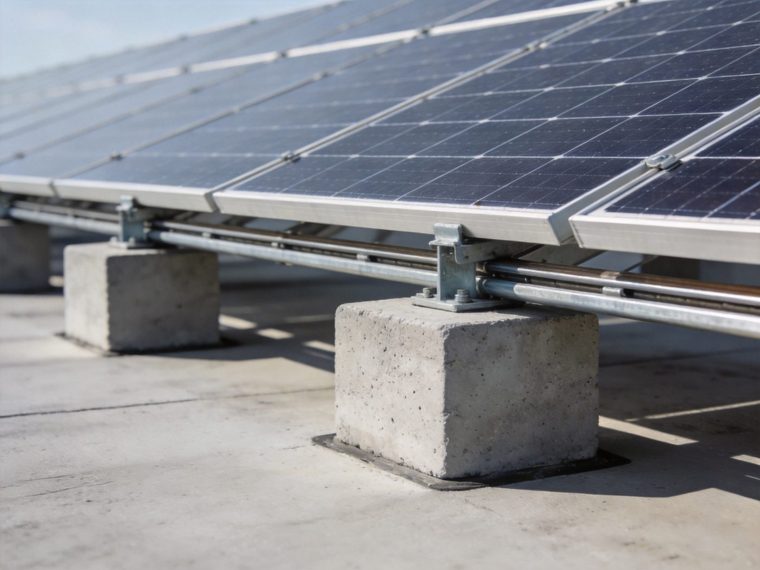
Ballasted solar foundations are non-penetrating structural systems that resist wind uplift, sliding, and overturning exclusively through dead weight — no soil anchoring, no ground penetration, no concrete curing, no pile driving. The ballast block assembly bears directly on the roof membrane, compacted soil, or hardstand surface, developing friction resistance at the base contact interface and gravitational resistance to uplift that together provide the structural stability required by the solar mounting system above. Ballasted systems are a non-penetrating solution within modern solar foundation systems, widely used in rooftop commercial installations, environmentally sensitive land sites, and temporary solar deployments where surface penetration is prohibited by lease terms, environmental regulation, or structural constraints. For a complete overview of all foundation options and their selection criteria by soil condition, structural demand, and project type, visit our Solar Foundation Systems Guide — the authoritative engineering reference for all solar foundation selection decisions.
The structural trade-off that defines ballasted foundation engineering: every kilogram of wind uplift resistance must be provided by a kilogram of ballast material placed on the supporting structure — making ballast weight calculation, roof structural capacity verification, and wind load analysis the three engineering decisions that determine whether a ballasted system is structurally viable and economically justified at any given project site. Where these constraints are satisfied, ballasted systems offer the fastest installation, the most complete site reversibility, and the lowest installation labor cost of all solar foundation types.
Technical Snapshot: Ballasted Foundation Key Parameters for Solar Mounting
| Parameter | Typical Value / Range | Governing Condition | Engineering Note |
|---|---|---|---|
| Embedment Depth | 0 m — non-penetrating; surface bearing only | N/A — no soil penetration | The defining structural characteristic of ballasted systems; no soil anchoring means all structural resistance comes from dead weight and friction at the bearing surface — the complete opposite of pile or screw foundation structural logic |
| Ballast Weight per Module | 15–60 kg/module for standard commercial rooftop at Vdesign = 90–130 mph; up to 120 kg/module in high-wind coastal C&I applications | Wind design speed, exposure category, tilt angle, array position (interior vs perimeter); ASCE 7-22 component and cladding uplift pressure at roof zone | Ballast weight is the primary design output — not a secondary check; at Vult > 140 mph, required ballast weight per module can exceed roof live load allowance, making ballasted systems structurally infeasible regardless of commercial preference |
| Roof Live Load Addition | 0.5–3.5 kPa total added load on roof structure (dead load of ballast + racking hardware) | Ballast weight per module ÷ module tributary area; must not exceed roof structural reserve capacity (typically 0.5–1.5 kPa available above existing dead load) | Roof structural reserve capacity is the binding constraint at most commercial buildings — the structural engineer of record for the building must confirm available capacity before ballasted system design begins; this confirmation is the single most common cause of project redesign or foundation type change in C&I solar |
| Base Friction Coefficient | µ = 0.45–0.70 for rubber pad on smooth concrete deck; µ = 0.55–0.75 for rubber pad on ballasted gravel surface; µ = 0.30–0.50 for plastic tray on TPO / EPDM membrane | Surface type; rubber pad material; contamination (wet surface reduces µ by 15–25%); age of rubber pad | Friction coefficient governs sliding resistance — the lateral wind force (from wind pressure on panel face) must be resisted by µ × Wtotal (friction force from total vertical load); wet or contaminated rubber pads at µ = 0.35 may be 40% less effective than clean dry pads at µ = 0.60; always design to worst-case friction condition |
| Tilt Angle Range | 5°–15° standard; up to 20° in low-wind interior regions; 5°–10° preferred in Vult > 120 mph zones to minimize wind uplift coefficient CN | Wind uplift increases rapidly with tilt angle — doubling tilt from 5° to 10° increases net uplift CN by approximately 35–50%; lower tilt reduces required ballast weight but also reduces energy yield | The tilt angle optimization for ballasted systems is a structural-energy trade-off unique to this foundation type — unlike penetrating foundations where tilt angle is unconstrained by structural considerations, ballasted systems impose a wind-driven upper bound on tilt that typically limits annual energy yield to 2–5% below the theoretical optimum tilt angle for the latitude |
| Suitable Surface | Flat to low-slope roof (≤ 5° slope) with membrane, concrete deck, or ballasted gravel; flat compacted soil or hardstand ground surface for temporary ground installations | Surface flatness (<20 mm differential over 3 m); load-bearing capacity; friction surface compatibility | Membrane roof surfaces (TPO, EPDM, PVC) require rubber isolation pads between ballast tray and membrane to prevent membrane puncture and abrasion; direct contact between concrete ballast block and membrane is prohibited |
| Design Service Life | 20–30 years for steel racking and concrete ballast; rubber pad replacement at 10–15 years; ballast concrete block life ≥ 40 years if not cracked | Corrosion of steel racking governs structural life in C3–C5 environments; rubber pad degradation (UV, ozone, thermal cycling) governs friction performance | Shorter design life than penetrating foundations reflects the rubber pad and steel racking exposure conditions on a rooftop (higher UV, thermal cycling range, possible standing water), not the ballast concrete life; specifying marine-grade aluminum racking with HDG or anodized finish extends structural life to 25–30 years in most rooftop environments |
What Is a Ballasted Solar Foundation?
Core Structural Concept: Dead Weight as the Sole Resistance Mechanism
A ballasted solar foundation is a structural system in which all resistance to applied loads — wind uplift, wind lateral (sliding) force, and overturning moment — is provided exclusively by the weight of the ballast material (concrete blocks, precast pavers, or gravel-filled trays) placed on the bearing surface, without any connection between the foundation assembly and the substrate below. This is the fundamental structural distinction between ballasted and all other solar foundation types: pile driven foundations resist loads through soil-pile interface friction and lateral soil reaction; concrete foundations resist loads through bearing, passive earth pressure, and concrete mass anchored to the ground; ground screw foundations resist loads through helical bearing plates embedded in soil. Ballasted foundations resist all loads through gravity alone — no soil connection, no structural attachment, no embedment. The structural consequence of this mechanism: ballast weight must equal or exceed the factored uplift demand (with safety factor FS ≥ 1.5) and the ballast friction force (µ × Wballast) must equal or exceed the factored lateral wind force. Every kilogram of structural resistance in a ballasted system is a kilogram of physical mass that must be transported to the site, lifted to the roof (for rooftop applications), and distributed across the roof structure — making the roof structural capacity check and ballast logistics the two project-defining constraints.
Main Structural Components of a Ballasted Foundation Assembly
A complete ballasted solar foundation assembly comprises five integrated components: (1) Concrete ballast blocks: precast concrete blocks (typically 200×400×600 mm, mass 20–30 kg each; or larger 400×600×800 mm blocks at 75–95 kg each) providing the primary dead weight resistance; concrete density ≈ 2,400 kg/m³; ballast blocks are precision-cast with consistent dimensions for stable stacking and accurate weight calculation; some systems use gravel-filled steel trays as an alternative to precast blocks, allowing weight adjustment in the field; (2) Steel support frame (tray): hot-dip galvanized or powder-coated steel frame that supports the module rails at the specified tilt angle and distributes the combined weight of modules, racking, and ballast over the roof surface; the frame must be stiff enough to maintain module alignment under wind-induced deflection; (3) Rubber isolation pads: EPDM or neoprene rubber pads (typically 5–10 mm thick, Shore A hardness 40–60) placed between the steel frame base feet and the roof surface; provide friction resistance against sliding, protect the roof membrane from abrasion and puncture, and distribute point loads from base feet over a wider membrane contact area; rubber pad contact area and friction coefficient are the inputs to the sliding resistance calculation; (4) Module rail and clamp system: extruded aluminum rails (standard 35×60 mm or 40×80 mm section) at specified tilt angle; module mid-clamps and end-clamps per module manufacturer’s specifications; (5) Inter-row wind deflectors (wind blocker panels): solid panel or perforated wind blocker strips installed at the rear edge of each panel row to reduce wind pressure on the underside of the panels, reducing net uplift CN by 20–40% and allowing proportional reduction in required ballast weight — a structural optimization that is unique to ballasted systems and often makes the difference between structural feasibility and infeasibility at moderate-wind sites.
When Engineers Choose Ballasted Systems Over Penetrating Foundations
Structural engineers and system designers specify ballasted foundations when one of three conditions make ground penetration impossible, unacceptable, or structurally unnecessary: (1) Rooftop installations with membrane waterproofing: flat commercial and industrial roofs with TPO, EPDM, PVC, or bituminous membrane waterproofing layers cannot be penetrated without voiding the roof warranty and creating leak risk; ballasted systems are the standard engineering solution for all flat-roof solar installations where the roofing system prohibits penetrations — which encompasses the majority of commercial and industrial rooftop solar globally; (2) Environmentally sensitive or protected land: brownfield remediation sites with contaminated soil that must not be disturbed; wetland buffer zones; archaeological protection zones; sites where lease terms prohibit surface penetration; in all these conditions, ballasted systems enable solar installation without triggering the regulatory requirements or lease violations that penetration would cause; (3) Temporary or relocatable installations: event power systems, construction site solar, military forward operating base solar, or any installation that must be demounted and relocated — ballasted systems can be fully demounted and reinstalled at a new location with minimal site impact, which no penetrating foundation type can match. The load transfer principles that govern how ballasted systems must distribute wind loads through the assembly — and the critical difference between dead-weight-based load transfer and soil-anchored load transfer — define why ballasted systems have a structurally defined upper wind speed limit that penetrating foundation types do not. Site surface condition assessment — including roof structural capacity verification and soil surface bearing capacity for ground-level ballasted systems — requires the same rigor as soil surface evaluation for penetrating foundation type selection.
Engineering Principles Behind Ballasted Solar Foundation Systems
Dead Load as Primary Structural Resistance: The Ballast Weight Equation
The fundamental ballast weight equation for wind uplift resistance under ASCE 7-22 LRFD governing uplift combination (0.9D + 1.0W): net stabilizing weight Wnet = 0.9 × (Wballast + Wmodules + Wracking) ≥ 1.0 × Fuplift. Rearranging to find required ballast weight: Wballast ≥ (Fuplift/0.9) − Wmodules − Wracking. For a standard commercial rooftop installation at Vult = 115 mph, Exposure B (suburban), roof zone 2 (field of roof), 10° tilt, 2.0 m × 1.0 m module: CN,uplift = −1.2 (net uplift coefficient from ASCE 7-22 Figure 29.4-7 equivalent); qz = 0.00256 × Kz × Kzt × V² = 0.00256 × 0.85 × 1.0 × 115² = 28.8 psf = 1.38 kPa; Fuplift per module = 1.38 × 1.2 × (2.0 × 1.0) = 3.31 kN; Wmodules = 0.22 kN (22 kg); Wracking = 0.10 kN (10 kg); Wballast,req = (3.31/0.9) − 0.22 − 0.10 = 3.68 − 0.32 = 3.36 kN = 343 kg per module. At perimeter rows (roof zone 3), CN,uplift = −2.0 (corner): Fuplift = 1.38 × 2.0 × 2.0 = 5.52 kN; Wballast,req = (5.52/0.9) − 0.32 = 5.81 kN = 592 kg per module at corners — potentially exceeding roof structural reserve capacity and requiring the perimeter modules to be eliminated or the tilt angle reduced to lower CN. This calculation defines the structural feasibility boundary for ballasted systems.
Wind Uplift Mechanics: Roof Zone Pressure Distribution
Wind uplift on a ballasted solar array varies dramatically across the roof zone — from minimum uplift at interior modules to maximum uplift at perimeter and corner rows — because wind pressure on low-slope roofs per ASCE 7-22 Chapter 29 follows the rooftop wind pressure zone pattern with dramatically higher Cp and GCpf at roof edges and corners. For a solar array on a flat commercial roof, the applicable standard is ASCE 7-22 Section 29.4.4 (roof-mounted solar panels on buildings with h ≤ 60 ft) or SEAOC PV2-2017 (Solar Photovoltaic Systems) for more detailed zone-by-zone pressure analysis. The critical engineering implication: ballast weight cannot be uniform across the entire array — perimeter and corner modules require 50–150% more ballast than interior modules. Applying uniform interior-zone ballast to the entire array (a common mistake in simplified ballast calculations) creates structurally under-ballasted corner and perimeter modules that are the first to displace in a wind event. Correct ballast design specifies three ballast levels: interior zone (minimum), edge zone (intermediate), and corner zone (maximum) — matched to the three wind pressure zones of the ASCE 7-22 roof zone map for the specific building dimensions and roof height.
Sliding and Friction Resistance
Lateral wind force (from wind pressure on the panel face) drives the entire ballasted assembly horizontally across the roof surface — a failure mode called sliding that is distinct from uplift and must be independently verified. Sliding resistance = µ × Ntotal (where µ = friction coefficient at rubber pad-to-roof interface; Ntotal = total vertical force = Wballast + Wmodules + Wracking − Fuplift,concurrent). The concurrent uplift force reduces the normal force pressing the rubber pad against the roof surface, simultaneously reducing friction resistance and increasing lateral demand — the combined sliding check must use concurrent uplift and lateral force from the same wind event, not independent maxima. Under ASCE 7-22 combined loading at a 10° tilt ballasted array in Vult = 115 mph Exposure B: Flateral per module ≈ 0.8 kN; Fuplift,concurrent ≈ 2.2 kN; Navailable = 3.68 − 2.2/0.9 = 3.68 − 2.44 = 1.24 kN; friction resistance at µ = 0.55: 0.55 × 1.24 = 0.68 kN < Flateral = 0.80 kN — sliding check fails; additional ballast or array interconnection (cable ties between adjacent frames to distribute lateral load to interior modules with higher available friction) is required. This calculation demonstrates that sliding can govern ballast design independently of uplift at low-tilt high-wind configurations. For a comprehensive treatment of all foundation structural mechanics including the comparison between ballasted dead-weight-based resistance and soil-anchored resistance, refer to the complete solar foundation guide.
Load Distribution on Roof Structures
Ballasted solar foundations add distributed dead load to the roof structure equal to (Wballast + Wmodules + Wracking) ÷ Amodule tributary area in kPa. For the example above: (343 + 22 + 10) kg × 9.81/1,000 per module ÷ (2.0 × 1.0 m²) = 3.75 kN ÷ 2.0 m² = 1.87 kPa added dead load. A typical commercial roof designed to IBC minimum live load of 0.96 kPa (20 psf) with existing roofing dead load of 0.5–1.0 kPa has available reserve capacity of 0.3–0.8 kPa — significantly less than the 1.87 kPa required. This is the fundamental structural constraint of ballasted systems on commercial rooftops: the required ballast weight frequently exceeds the roof structure’s reserve capacity, requiring either structural reinforcement of the roof framing, reduction in array density (fewer modules per roof area), tilt angle reduction (reducing required ballast), or foundation type change to a penetrating system. Load distribution must also address concentrated loads at base feet: if each base foot contacts the roof at a 150×150 mm rubber pad area, the contact pressure = Ffoot/Apad — point load concentrations at the interface between base feet and roof purlins must be verified not to exceed the allowable local bearing stress on the roof deck or membrane.
Structural Anatomy & Non-Penetrating Design
Ballast Block Geometry: Size, Mass, and Layout Optimization
Ballast block geometry is determined by three simultaneous constraints: (1) Structural mass requirement: total ballast mass per module position must meet the calculated Wballast,req from the uplift and sliding checks; (2) Individual block mass limit: manual handling safety regulations typically limit individual block mass to 25 kg for a single person and 50 kg for two-person lift — this drives the use of multiple smaller blocks rather than a single large block in most applications; automated block-handling equipment removes this constraint for large-scale projects; (3) Roof structural load distribution: ballast blocks must be positioned over or close to roof structural members (beams, purlins) to ensure load is transferred into the structural framing rather than spanning across unsupported roof deck. Standard block configurations: 200×400×100 mm precast concrete (mass ≈ 19 kg) for light-duty rooftop applications; 400×600×150 mm (mass ≈ 86 kg, two-person handling) for medium commercial rooftop; modular interlocking ballast systems (HDPE or polypropylene blocks filled with gravel on-site) for applications where lifting precast concrete to roof level is impractical. Interlocking modular systems allow empty blocks to be lifted individually (2–5 kg each) and filled with gravel on the roof surface — reducing individual lift weight to a single-person safe load while achieving any target ballast mass by varying fill depth.
Steel Support Frame: Tilt Geometry and Load Path
The steel support frame (tray or chassis) of a ballasted solar system provides three structural functions: (1) holds modules at the specified tilt angle with adequate stiffness to maintain alignment under wind loading; (2) distributes module wind load and dead load to the base foot locations (typically 4–6 base feet per module or per module pair); (3) transfers wind uplift from module to ballast block through the frame structure, maintaining vertical load equilibrium throughout the wind event. Frame structural design must verify: frame deflection under design wind load ≤ L/180 (where L = frame span between supports) to prevent module misalignment; base foot reaction forces including uplift and shear at each foot location for rubber pad sizing; frame member stresses under combined wind and dead load combinations per AISC 360-22 or equivalent. Hot-dip galvanized steel frames (HDG 85 µm) are standard for C1–C3 rooftop environments; pre-galvanized (Z275 or AZ150 Galvalume) is acceptable for interior applications; marine-grade aluminum alloy (6005A-T5 or 6061-T6) is preferred for C4–C5 coastal rooftop environments where steel HDG coating depletion is a concern within 15–20 years. Aluminum frame systems are 40–60% lighter than equivalent steel frames — directly reducing roof dead load addition, which is beneficial at roof structural capacity-limited sites.
Anti-Slip and Roof Protection Layers
The rubber isolation pad system between the base frame feet and the roof surface performs three simultaneous structural and protective functions: (1) Friction resistance: EPDM rubber (µ = 0.50–0.65 on smooth concrete; µ = 0.55–0.70 on ballasted gravel) provides the lateral sliding resistance that prevents the array from displacing horizontally under wind force; (2) Membrane protection: rubber pads prevent direct abrasion between the metal frame base and the roof waterproofing membrane (TPO/EPDM/PVC), which would cause membrane wear and eventual puncture; pad hardness must be adequate (Shore A ≥ 40) to prevent the metal frame edge from cutting into the rubber and transmitting force directly to the membrane; (3) Load distribution: rubber pads distribute the concentrated base foot reaction force over a larger area, reducing contact pressure on the membrane below the allowable puncture threshold (typically 2–5 kPa for standard commercial roofing membranes). Rubber pad area is specified by: Apad,min = Ffoot,max/pallow,membrane where Ffoot,max = maximum base foot reaction under combined dead + wind load; pallow,membrane = allowable contact pressure per membrane manufacturer specification. The long-term durability of rubber pad friction performance — which degrades with UV exposure, ozone, thermal cycling, and contamination — and the maintenance inspection protocol for rubber pad replacement are addressed in the foundation corrosion protection strategies resource covering material degradation management for all non-penetrating foundation components.
Drainage and Water Flow Considerations
Ballasted solar arrays on flat roofs create a significant drainage management challenge: the array tilt geometry directs rainfall runoff to the rear (low-edge) of each panel row in a concentrated stream rather than dispersing it across the roof surface. Without drainage design, concentrated rear-edge runoff can: (1) erode the roof membrane at the ballast frame base foot contact points; (2) create standing water pools between array rows that exceed the roof design ponding load (typically 0.25–0.50 kPa); (3) accelerate rubber pad deterioration through sustained water contact; (4) create ice build-up between rows in freeze-thaw climates that increases effective ballast weight above the design value. Drainage design requirements for ballasted rooftop solar: minimum 600 mm clearance between rear module edge and adjacent front module edge (inter-row gap) for drainage flow path; scuppers or secondary drains positioned at row ends to capture rear-edge concentrated runoff; minimum 1% roof slope toward drains maintained under the array (confirmed by roof survey before installation); no ballast blocks placed over primary roof drains.
Installation Workflow
Phase 1 — Roof Structural Assessment and Engineering Pre-Qualification
The pre-installation engineering review for a ballasted rooftop solar system requires three completed deliverables before procurement of any hardware: (1) Building structural engineer review: the structural engineer of record for the building (or a licensed structural engineer retained for the project) must verify roof framing capacity for the proposed added dead load from ballast, racking, and modules; confirm that existing roof members (beams, joists, purlins, deck) have sufficient reserve capacity to carry the added ballast load with structural safety factor ≥ 1.5 against governing limit states; identify any roof zones where ballast placement is structurally prohibited; (2) Roofing contractor / membrane manufacturer review: the roofing contractor responsible for the building’s roof warranty must confirm that the ballasted system installation method is compatible with the existing roof warranty — most membrane manufacturers (GAF, Firestone, Carlisle, Sika) have approved ballasted solar systems lists and installation protocols that, if followed, maintain the existing roof warranty; deviation from the approved system or installation method voids the warranty; (3) Wind and ballast calculation: site-specific wind pressure calculation per ASCE 7-22 for the building height, exposure category, and roof zone configuration; required ballast weight by zone (interior, edge, corner) calculated per SEAOC PV2-2017 or equivalent methodology; confirmed ballast weight compared to roof structural capacity; if required ballast exceeds roof structural allowance, system redesign required before procurement. The foundation selection guide provides the structured decision framework for evaluating whether ballasted foundations are the appropriate solution for a given building type, roof condition, and wind environment — including the threshold conditions at which penetrating or low-ballast alternatives become the structurally preferred option.
Phase 2 — Ballast Block Delivery, Placement, and Array Layout
Ballast block delivery to rooftop is typically the most logistically challenging element of ballasted system installation: concrete ballast blocks are heavy (20–95 kg each), numerous (15–40 blocks per module at high-wind sites), and must be lifted to roof level (typically 5–30 m) using a crane, forklift with boom attachment, or conveyor system. For a 500 kWp rooftop array at 35 kg/module average ballast (approximately 1,250 modules): total ballast mass = 1,250 × 35 = 43,750 kg — a 44-tonne material delivery to the roof surface that must be planned for structural load staging (delivering and distributing in phases to avoid exceeding roof temporary construction load limits) and logistical access (crane reach to all roof zones). Actual installation sequence: (1) crane or conveyor delivery of ballast blocks to roof level, staged in structural bays at or below roof allowable load; (2) steel frame tray units placed at survey-marked module positions, rubber pads positioned under all base feet; (3) ballast blocks loaded onto frame trays per zone-specific ballast map; (4) rails and module clamps installed; (5) modules lifted and clipped to rails; (6) electrical connections and grounding. Total installation crew: 6–10 workers per 500 kWp system; typical installation rate: 50–80 kWp per crew-day for standard commercial flat roof system.
Phase 3 — Module Mounting, QA Verification, and Final Inspection
Post-installation quality assurance for ballasted systems requires three verification activities: (1) Ballast count verification: 100% count of ballast blocks per module position against the zone-specific ballast map; under-ballasted positions (a common field error when installation crews run short of blocks and skip zones) are the single leading cause of ballasted system wind event damage — every position must be verified against the design count before energization; (2) Rubber pad contact inspection: visual inspection of 20% sample of base foot rubber pad contacts to confirm pad is present, correctly positioned, and in full contact with roof surface; base feet with no pad, partial pad, or pad displaced from contact position must be corrected; (3) Drainage flow test: water flow test at a representative inter-row gap to confirm drainage path is clear and water does not pond between rows; any standing water location must be investigated for roof drainage deficiency before array energization.
Performance Analysis
Wind Resistance Limitations: The Structural Upper Bound
Ballasted solar foundations have a structural wind resistance upper bound that no other solar foundation type imposes — the point at which required ballast weight exceeds the roof structural reserve capacity or becomes logistically impractical. This upper bound is project-specific, but generalized guidelines based on ASCE 7-22 analysis for standard commercial rooftop applications: at Vult ≤ 110 mph Exposure B (standard suburban commercial), 10° tilt, interior zone: Wballast,req ≈ 15–25 kg/module — generally within roof structural capacity; at Vult = 130 mph Exposure B or Vult = 115 mph Exposure C: Wballast,req ≈ 35–55 kg/module interior, 80–120 kg/module at perimeter — approaching or exceeding typical roof reserve capacity; at Vult ≥ 150 mph or Exposure D (coastal): Wballast,req may exceed 150 kg/module at perimeter zones — structurally infeasible on virtually all standard commercial buildings. Wind blocker panels can reduce CN and required ballast by 20–35%, extending the viable wind speed range upward; however, above Vult ≈ 140 mph, penetrating foundation systems are typically the only structurally viable option for permanent installations. The site-specific wind pressure calculation that determines whether a ballasted system is structurally viable at any given location is performed using the methodology in the wind load calculation standards resource.
Snow Accumulation Behavior
Snow load on a ballasted solar array has a uniquely favorable interaction with the ballasted foundation structural system: snow adds downward (compressive) load to the assembly, increasing the normal force at the rubber pad-bearing surface interface and increasing friction resistance against lateral sliding — the opposite structural effect of wind uplift, which reduces normal force. Under combined snow + wind loading, the sliding resistance check generally becomes less critical (more friction available) while the roof structural capacity check becomes more critical (more total load on roof structure). The governing roof structural load combination: 1.2D + 1.6S + W (ASCE 7-22 LRFD Combination 3 with companion wind action) — roof must carry permanent ballast dead load (D) plus maximum design snow accumulation (S) plus concurrent wind force (W) simultaneously. Snow depth management — maintaining minimum module clearance above roof surface to prevent snow re-accumulation blocking runoff — requires that ballast frame height provide minimum 100–150 mm clearance between module underside and roof surface in the highest-snow-load design condition.
Long-Term Roof Load Impact
The 25-year sustained dead load from a ballasted solar array on a roof structure creates two long-term structural effects that must be considered in the building structural assessment: (1) Long-term deflection of roof framing: steel roof beams and joists under sustained load experience creep deflection (for composite or timber elements) or elastic deflection that accumulates at mid-span; for steel-framed roofs, long-term deflection under sustained ballast load is typically 5–15 mm at mid-span of standard joist spans — sufficient to affect roof drainage slope and potentially cause ponding at low-slope roof zones; (2) Cumulative fatigue at roof connections: the combination of sustained ballast dead load and wind-induced cyclic loading (10⁶–10⁷ cycles over 25 years at wind-exposed rooftops) produces cumulative fatigue stress at roof joist-to-beam connections and at the roof deck fastener connections; for roofs originally designed without the solar ballast dead load, these connections may approach fatigue limit state earlier than the roof’s original design life.
Advantages & Limitations
Structural and Commercial Advantages
- No ground or roof penetration: the defining advantage — membrane roof waterproofing integrity is maintained; soil contamination is undisturbed; lease terms prohibiting penetration are satisfied; environmental protection zone regulations are complied with; building roof warranty is preserved when manufacturer-approved installation method is followed
- Fastest deployment of all foundation types at equivalent scale: no excavation, no concrete mixing, no pile driving equipment, no soil investigation required; installation begins immediately upon ballast block delivery; 500 kWp commercial rooftop system installed in 3–5 days with standard crew; no curing delay, no soil investigation lead time, no heavy equipment mobilization
- Complete reversibility and relocatability: ballasted arrays can be fully demounted in 1–2 days per 500 kWp with no residual physical impact on the roof or ground surface; modules, racking, and ballast blocks are all reusable at a new location; building roof is restored to pre-installation condition after demounting (rubber pad marks may remain but no structural modification); no decommissioning cost for foundation removal
- Enables solar on buildings with complex ownership structures: leased buildings where tenants cannot modify the building structure (no penetrations) can install ballasted rooftop solar without landlord structural modification approval; ballasted installation is classified as “personal property” (removable equipment) rather than “building improvement” in most jurisdictions — with favorable tax and depreciation treatment
- Low installation labor cost: no specialized foundation installation equipment required; standard construction labor with material handling equipment; no geotechnical investigation, no special inspections (in most jurisdictions for standard ballasted applications), no concrete QA testing — significantly reducing soft cost relative to penetrating foundation alternatives
Structural and Commercial Limitations
- Wind resistance upper bound: structurally infeasible at Vult > 130–140 mph in most rooftop configurations due to ballast weight exceeding roof structural capacity; perimeter and corner zones always require substantially more ballast than interior zones, concentrating structural demand at the worst locations for roof load management
- Roof structural capacity binding constraint: the majority of project redesigns, scope reductions, or foundation type changes in C&I solar originate from ballast weight exceeding roof structural reserve — a constraint that is not apparent until the building structural engineer review is completed, often late in the project development cycle
- Tilt angle limitation: low tilt (5°–12°) required to limit wind uplift coefficients and ballast requirements; low tilt reduces annual energy yield by 5–15% relative to latitude-optimal tilt angle in mid-latitude markets — a permanent energy production penalty that accumulates over the 25-year project life
- Rubber pad degradation requires maintenance: rubber pads must be inspected and replaced at 10–15-year intervals to maintain specified friction coefficient; degraded pads (cracked, hardened, contaminated) provide significantly reduced sliding resistance that may fall below design requirements; post-maintenance ballast count re-verification required after any roof work that disturbs the array
- Not suitable for sloped surfaces: structural stability on slopes >5° is problematic — gravity component along the slope adds to wind lateral force, requiring either increased ballast (resisting combined gravity + wind lateral) or mechanical restraint that introduces penetration
Best Application Scenarios
Flat Roof Commercial and Industrial Buildings
Flat-roof commercial and industrial buildings — warehouses, distribution centers, manufacturing facilities, office buildings, retail stores — are the primary application market for ballasted solar foundations globally. The combination of large, unobstructed roof area; flat geometry compatible with ballasted array layout; membrane waterproofing that cannot be penetrated; and commercial energy demand that solar can offset on-site makes C&I rooftop solar with ballasted foundations one of the highest-ROI solar applications available. For a full understanding of the racking engineering, electrical layout, and structural requirements that govern commercial solar mounting projects — including the building structural assessment process and the ballasted system selection criteria for different building types — the commercial solar mounting resource provides the complete engineering framework.
Environmentally Sensitive and Penetration-Restricted Land
Ground-level ballasted solar installations are used at sites where surface penetration is restricted: brownfield redevelopment sites (pile driving or screw installation would disturb contaminated soil layers); landfill cap solar (membrane cap cannot be penetrated); agricultural land with underground drainage tile systems that pile driving would damage; sites with shallow utility infrastructure. For ground-level ballasted systems, the structural design is essentially identical to rooftop applications (dead weight uplift resistance + friction sliding resistance), but wind speeds and exposure categories are typically more severe than rooftop (Exposure C or D for ground-level open terrain), increasing required ballast weight and limiting viable wind speed range to approximately Vult ≤ 100–110 mph for practical ballast weights on compacted soil.
Temporary and Relocatable Solar Installations
Ballasted foundations are the only solar foundation type that enables true temporary installation — complete assembly, operation for a defined period, and full demounting with restoration of the bearing surface to pre-installation condition. Applications include: construction site temporary power; event and festival solar power; military and emergency response forward base power; demonstration installations at trade shows or solar test facilities; solar installations on buildings with limited remaining lease terms where demolition after 5–10 years is planned. For temporary applications with design life ≤ 10 years, standard structural calculations apply but corrosion protection specifications may be reduced — aluminum racking with anodized finish provides adequate service life for 10-year temporary installations without the galvanizing specification required for 25-year permanent systems.
Cost & ROI Considerations
Ballasted foundation cost for solar mounting comprises four components: ballast material, racking hardware (frame, rails, clamps), rubber pads, and installation labor. Unlike penetrating foundation types, ballasted systems require no geotechnical investigation, no excavation, no concrete, and no specialized installation equipment — reducing both hard cost (material) and soft cost (investigation, inspection, specialized labor) significantly. Typical cost breakdown for a 500 kWp commercial rooftop ballasted installation in the continental US:
| Cost Component | Unit Cost | Total at 500 kWp (~1,250 modules) | $/Wp |
|---|---|---|---|
| Precast concrete ballast blocks (avg 35 kg/module, $0.18/kg delivered to roof) | $6.30/module | $7,875 | $0.016 |
| Steel/aluminum racking frame and rails (HDG steel standard; Al optional) | $28–$45/module | $35,000–$56,250 | $0.070–$0.113 |
| Rubber isolation pads ($2.50 per pad, 4 pads per module average) | $10.00/module | $12,500 | $0.025 |
| Crane / material handling (ballast lift to roof) | $4.50/module | $5,625 | $0.011 |
| Installation labor (6-person crew, 8 days) | $8.00/module | $10,000 | $0.020 |
| Building structural engineering review | $3.20/module | $4,000 | $0.008 |
| Total ballasted foundation cost | $60–$83/module | $75,000–$96,250 | $0.150–$0.193/Wp |
At $0.150–$0.193/Wp, ballasted rooftop foundations appear higher cost per watt than ground-mount penetrating foundations ($0.011–$0.035/Wp) — but this comparison is not structurally meaningful because rooftop and ground-mount systems are not substitutable. Within the rooftop application category, ballasted foundations are 20–35% less expensive than penetrating rooftop foundations (which require waterproofing-compatible penetration seals, structural attachments, and roof warranty management at $0.18–$0.25/Wp). The lifecycle cost advantage of ballasted systems in the rooftop context also includes zero decommissioning cost versus penetrating systems’ $0.008–$0.015/Wp roof restoration cost at end of project life. For a full cross-type cost analysis, see the foundation cost comparison resource; for the specific structural and commercial trade-off between ballasted and penetrating roof foundations, see the ballasted vs penetrating foundation comparison.
Comparative Engineering Matrix
| Criterion | Ballasted | Concrete | Pile Driven | Ground Screw |
|---|---|---|---|---|
| Ground/Roof Penetration Required | ✅ None | ❌ Yes — excavation | ❌ Yes — driven embedment | ❌ Yes — screwed embedment |
| CapEx (relative) | Medium — ballast material cost | High — concrete + rebar + excavation | Medium — pile section + driving | Medium — screw hardware + torque rig |
| Installation Speed | ✅ Fast — no curing, no driving | ❌ Slow — 10–21 day cure delay | ✅ Fast — 200–500/day per rig | ✅ Fast — 150–350/day per rig |
| Soil / Surface Requirement | ✅ None — surface bearing only | Required — adequate bearing capacity | Required — N = 5–40 for driving | Required — torque-correlatable soil |
| Wind Resistance (high Vult) | ❌ Limited — >140 mph infeasible in most roof applications | ✅ Very High | ✅ High | Medium |
| Suitable for Rooftop | ✅ Yes — primary application | ❌ No | ❌ No | ❌ No |
| Site Reversibility | ✅ Very High — complete removal, no residual | ❌ Low — concrete demolition required | Medium — extraction possible | ✅ High — reversible extraction |
| Geotechnical Investigation Required | ✅ No (roof: structural review only) | ❌ Yes — mandatory | ❌ Yes — mandatory | ❌ Yes — torque correlation required |
Ballasted foundations are uniquely positioned in the solar foundation spectrum: the only viable option for rooftop and penetration-prohibited sites, but structurally limited at high wind speeds where penetrating alternatives are required. For a complete evaluation of all foundation types and their optimal application conditions, refer to our Solar Foundation Systems Guide.
Engineering Design Checklist
- Roof structural capacity verified by licensed structural engineer: added dead load from ballast + modules + racking ≤ available roof structural reserve capacity; load path traced from module through frame through ballast to roof framing members confirmed adequate; written structural engineer confirmation obtained before hardware procurement
- Wind speed and exposure category confirmed for project location: Vult from ASCE 7-22 Figure 26.5-1B (Risk Category II); exposure category (B/C/D) from site survey; roof zone map (interior / edge / corner) generated for specific building plan dimensions and roof height
- Friction coefficient confirmed for proposed rubber pad on actual roof surface: specify rubber pad material and durometer; confirm µ value from manufacturer test data for the specific pad-to-surface combination; design to worst-case µ (wet surface, aged pad) not best-case
- Ballast weight calculated by roof zone: separate Wballast,req calculated for interior, edge, and corner zones using zone-specific CN values; uniform single-zone ballast weight not acceptable; ballast map generated showing block count per module position by zone
- Sliding resistance verified under concurrent uplift + lateral loading: friction resistance = µ × (Wtotal − Fuplift,concurrent/0.9) ≥ Flateral; concurrent loading, not independent maximum, used in calculation
- Seismic zone reviewed for applicability: SDC D–F sites require seismic lateral force check in addition to wind lateral check; seismic base shear per ASCE 7-22 §13.3 (non-structural component) applied to ballasted array mass; confirm friction resistance adequate for concurrent seismic + gravity without concurrent wind uplift reduction
- Drainage impact assessed and mitigation designed: inter-row drainage gap ≥ 600 mm; no ballast blocks over primary roof drains; roof slope toward drains ≥ 1% confirmed; scuppers or secondary drains at row ends specified if required by drainage flow analysis
- Rubber pad replacement and maintenance schedule included in O&M plan: visual inspection every 3 years; replacement at 10–15 years; ballast count re-verification after any roof maintenance work that disturbs the array
Failure Risks & Common Engineering Mistakes
Insufficient Ballast Weight: Uniform Ballast Applied to Non-Uniform Pressure Zones
The most common ballasted system structural failure mode is displacement of perimeter and corner modules during high wind events — caused by applying a single uniform ballast weight (calculated for the interior zone) to the entire array without increasing ballast at perimeter and corner positions. Interior CN,uplift ≈ 1.2; corner CN,uplift ≈ 2.0–2.5 at equivalent wind speed — a 65–110% higher uplift coefficient at corners than interior. Arrays with uniform interior-zone ballast have corner modules that are structurally under-ballasted by 65–110% relative to design requirement — meaning corner modules displace in wind events at approximately 78–87% of the design wind speed. The engineering control: generate a zone-specific ballast map as a project design deliverable, with independent block counts for interior, edge, and corner positions, and verify the counts in a 100% post-installation inspection.
Ignoring Roof Structural Limits: Installing Without Building Engineer Confirmation
Installing a ballasted solar system without formal confirmation from the building’s structural engineer of record that the roof framing can carry the added dead load is an engineering liability and, in most jurisdictions, a code violation (IBC 2024 §1604.1 requires that existing structures modified by added loads be verified for structural adequacy). The structural consequence of over-loading a roof beyond its capacity: progressive deflection at mid-span causing ponding (water accumulation that adds more load, causing more deflection in a progressive failure cycle); connection fatigue failure at joist-to-beam seats under combined sustained dead load and cyclic wind load; in extreme cases, joist flange local buckling under combined axial (gravity) and bending (wind uplift transferred through ballast frame to roof structure).
Improper Wind Assessment: Using a Generic or Incorrect Exposure Category
Wind pressure on a rooftop solar array is highly sensitive to the ASCE 7-22 exposure category designation: Exposure B (suburban, trees and buildings) versus Exposure C (open terrain, scattered obstructions) produces wind pressures that differ by 25–40% at equivalent building height and wind speed. Mis-classifying an open suburban industrial site as Exposure B (when the correct classification is C based on upwind terrain fetch) under-calculates wind pressure by 25–40%, under-calculates required ballast by an equivalent amount, and produces a structurally under-ballasted array. Exposure category determination requires a 360° upwind terrain fetch analysis for 1,600 m (approximately 1 mile) radius — not a desk assumption based on general location description.
Drainage Blockage: Ballast Blocks Placed Over or Adjacent to Roof Drains
Ballast blocks placed over or within 600 mm of primary roof drains block the drainage flow path, causing standing water accumulation under the array. At 25 mm water depth over a 500 m² array area: ponding load = 0.025 m × 9.81 kN/m³ × 500 = 123 kN = 12.5 tonnes — an unplanned structural load that adds to the ballast dead load and may collectively exceed the roof structural reserve capacity. In cold climates, standing water freezes into an ice sheet that adds even greater mass and physically lifts the ballast frames by ice expansion, displacing the array from its installed position. The drainage survey conducted before installation — confirming that no primary drains are within the array footprint, that inter-row gaps align with drainage flow direction, and that roof slope direction drives runoff toward accessible drainage points — is a mandatory pre-installation engineering step.
Frequently Asked Questions
How much ballast weight is required for a commercial rooftop solar system?
Required ballast weight per module depends on three primary variables: design wind speed (Vult), roof exposure category, and module position within the array (interior, edge, or corner). For a standard suburban commercial building (Exposure B, h = 10 m) at Vult = 110 mph with 10° tilt and wind blocker panels: interior zone ≈ 15–22 kg/module; edge zone ≈ 25–40 kg/module; corner zone ≈ 45–70 kg/module. Without wind blocker panels, add 25–35% to all values. At Vult = 130 mph on an open-terrain coastal site (Exposure C): interior zone ≈ 30–45 kg/module; corner zone ≈ 90–130 kg/module — at which point corner zone ballast frequently exceeds roof structural reserve capacity and perimeter rows must be eliminated or the system redesigned with a penetrating foundation at array edges.
Will a ballasted solar system void my roof warranty?
A ballasted solar system voids a roof warranty only if the installation does not follow the roofing membrane manufacturer’s approved installation protocols for solar arrays. All major membrane manufacturers (GAF, Firestone Building Products, Carlisle SynTec, Sika Sarnafil) maintain lists of approved ballasted solar racking systems that have been tested and approved for use over their membranes without voiding the warranty. Installing a manufacturer-approved system with the specified rubber isolation pads, minimum pad area, and maximum contact pressure per the approved installation guide maintains the full roof warranty. Installing a non-approved system, using incorrect pad materials, or exceeding the membrane manufacturer’s maximum point load specification voids the warranty. Confirm approved system status with the roofing contractor before hardware selection.
Can ballasted solar systems be used in snow climates?
Yes — ballasted systems are used in snow climates, but require additional engineering consideration for two snow-specific effects: (1) snow dead load adds to ballast dead load on the roof structure, requiring the combined (ballast + modules + snow) load to remain within roof structural capacity — verify that roof structural reserve includes the full design snow load per ASCE 7-22; (2) frost heave is not a concern for rooftop ballasted systems (roof deck does not frost heave), but for ground-level ballasted systems on frost-susceptible soil, the bearing surface can frost heave and displace the array, requiring ballast frame to accommodate ±30–50 mm differential heave movement between adjacent frames without structural distortion. In heavy-snow regions (pg ≥ 1.5 kPa), module tilt angle for ballasted systems should be ≥ 10° to encourage snow shedding and prevent excessive snow accumulation load on the array surface. For detailed frost depth and frost heave risk evaluation applicable to ground-level ballasted installations, see the frost protection design resource.
What is the maximum wind speed for a ballasted solar foundation?
There is no absolute maximum wind speed for ballasted solar foundations — the structural limit is defined by whether the required ballast weight exceeds the roof structural reserve capacity, which is building-specific. As a practical guideline for standard commercial buildings with 0.5–1.0 kPa roof structural reserve: Vult ≤ 115 mph (Exposure B) or Vult ≤ 100 mph (Exposure C) allows a full-coverage array with standard ballast at typical tilt angles; Vult = 115–130 mph (Exposure B) requires corner and perimeter row ballast that may exceed roof capacity, requiring row reduction or wind blocker panels; Vult > 130 mph is generally infeasible for full-roof coverage in standard buildings. Buildings with structural reinforcement providing 2.0–3.0 kPa reserve can accommodate ballasted systems at higher wind speeds. Site-specific calculation is the only definitive answer — generic wind speed limits should not be applied without project-specific analysis.
How long do ballasted solar systems last?
The structural service life of a ballasted solar system is governed by the shortest-life component: concrete ballast blocks (structural life >50 years if not cracked by freeze-thaw or physical impact); steel racking frame with HDG 85 µm coating (25–35 years in C2–C3 rooftop environment; 15–20 years in C4–C5 coastal rooftop); aluminum racking frame (30–40 years in C2–C4; 25–30 years in C5); rubber isolation pads (10–15 years before friction coefficient degrades to below-specification level — planned replacement required). Practically, a well-maintained ballasted system with aluminum racking or periodically re-coated steel racking and rubber pad replacement at 12-year intervals achieves the 25-year project design life in most rooftop environments outside severe coastal (C5) zones.
Can a ballasted foundation work on a slightly sloped roof?
Ballasted foundations are viable on roof slopes up to approximately 5° (9%) with standard design — the gravity component along the slope (W × sin θ) adds to the wind lateral force demand on the sliding resistance check, but at 5° slope: additional sliding demand = W × sin(5°) = 0.087W — approximately 8.7% addition to the lateral demand, manageable within standard friction reserve. Above 5° slope, the additional lateral demand from gravity slope component increases the required ballast weight for sliding resistance and may require ballast increase or mechanical lateral restraint. Above 10° roof slope, ballasted systems require project-specific sliding analysis with potential mechanical tie-back between array rows to prevent gravity-driven array migration — at which point penetrating attachment systems are typically more economical.
Prepare for project-specific review
Use this guide to organize the site, load, system and compliance inputs that a product supplier, licensed engineer, installer or local authority will need. PVRack does not provide project-specific engineering approval or supplier quotations.