
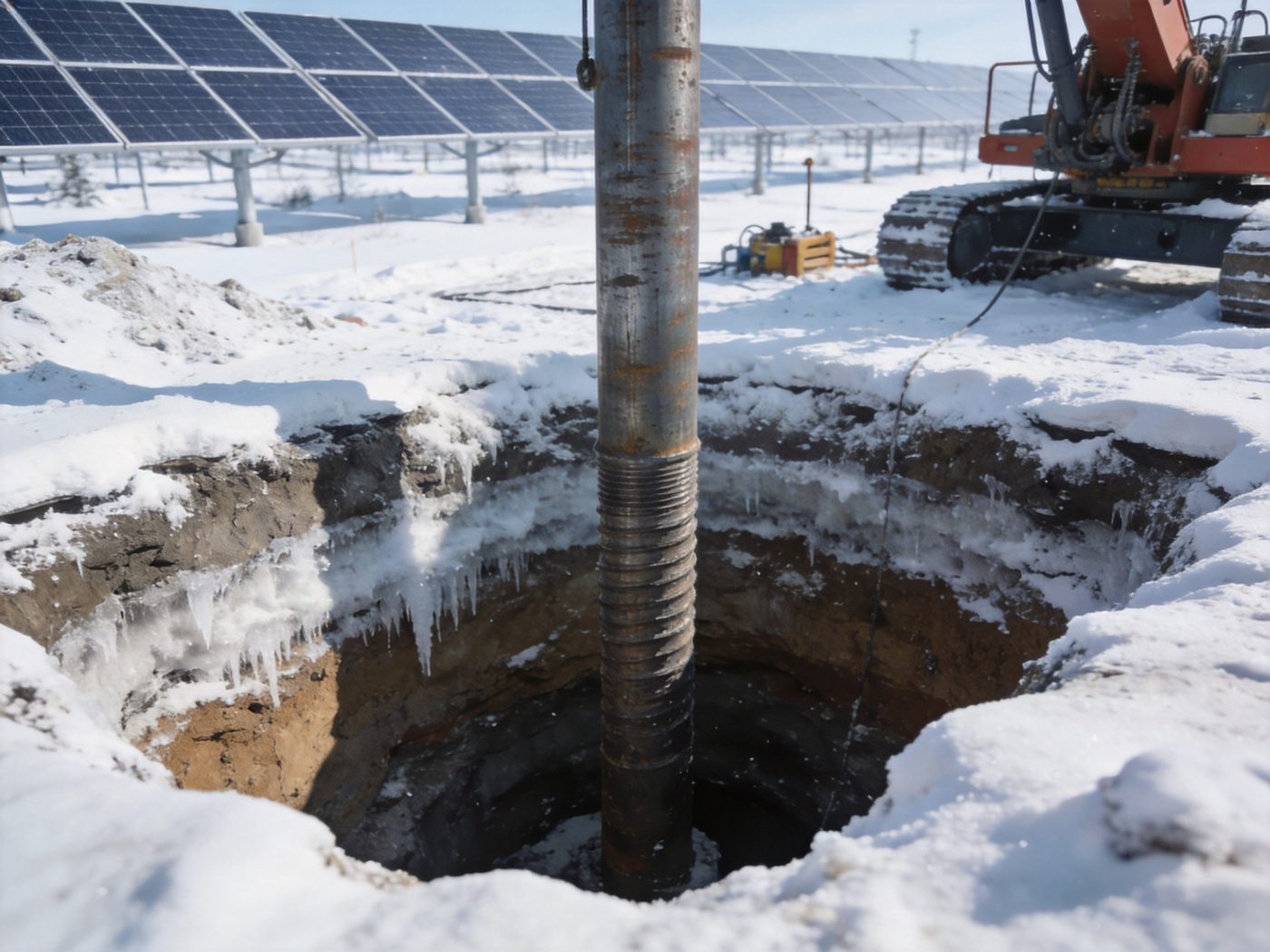
Frost protection is a critical design factor in cold-region solar foundation systems — improper frost depth evaluation is one of the leading causes of foundation heave, structural misalignment, and long-term instability in solar installations across northern latitudes, mountain terrain, and high-altitude sites where seasonal ground freezing is a recurring structural event. Unlike wind or seismic loading — which impose intermittent peak forces — frost heave imposes cyclic, persistent vertical displacement forces that act cumulatively over every winter season, progressively displacing foundation elements upward if they are not embedded below the frost line. A solar mounting column displaced 30–50 mm upward by frost heave appears structurally intact at the component level but misaligns the tracker drive mechanism, overstresses the racking-to-column bolted connection, and induces secondary bending in adjacent racking spans — damage that manifests slowly, may not be detected until the second or third winter cycle, and requires expensive remediation including pile extraction and re-driving, screw reinstallation, or structural shimming. For a full overview of all solar foundation types and their cold-climate design requirements, visit our Solar Foundation Systems Guide.
The engineering solution to frost heave risk is not complicated — place the structural bearing element (pile tip, screw helix, or concrete footing base) below the maximum frost penetration depth so that the frozen soil above cannot exert upward jacking force against the bearing element — but the implementation requires accurate determination of site-specific frost depth from climate data, soil frost susceptibility classification from geotechnical investigation, and embedment depth specification that integrates both the structural capacity requirement and the frost depth requirement simultaneously. Projects that treat frost depth as a post-design check rather than a governing design input consistently produce foundations that achieve the required structural capacity at insufficient embedment depth — the capacity criterion passes while the frost criterion fails, and the combined failure is not detected until seasonal heave damage occurs in service.
Technical Snapshot: Frost Protection Design Parameters for Solar Foundation Engineering
| Parameter | Typical Range / Value | Governing Design Decision | Engineering Note |
|---|---|---|---|
| Frost Penetration Depth (zf) | 0 m (tropical, no frost); 0.3–0.6 m (mild temperate: UK, Central Europe coastal, Pacific Northwest); 0.6–1.2 m (continental temperate: Central US, Central Europe inland, Korea, N. Japan); 1.2–2.0 m (subarctic: Canada, Scandinavia, northern Russia, Hokkaido); >2.0 m (arctic, high-altitude alpine) | Minimum foundation embedment depth; concrete footing minimum depth per IBC 2024 §1809.5; pile/screw target depth below frost zone | Frost depth is determined from the Air Freezing Index (AFI = cumulative degree-days below 0°C in the design winter) using the modified Berggren formula or local code tables; design frost depth uses the 100-year return period AFI, not the mean annual AFI — the difference is typically 20–40% in continental climates and can increase required embedment by 200–400 mm relative to mean AFI-based calculations |
| Air Freezing Index (AFI) | 0 (tropical); 100–500 °C·days (mild temperate); 500–1,500 °C·days (continental temperate); 1,500–4,000 °C·days (subarctic); >4,000 °C·days (arctic / high alpine) | Input to Modified Berggren frost depth formula: zf = λ × √(AFI / k × L) where k = thermal conductivity, L = latent heat of fusion of soil water | AFI is calculated from NOAA daily minimum temperature data (30-year climate normals for standard design; 100-year extreme for critical structures); design AFI should use the 2% annual probability of exceedance value (50-year return period minimum) or 1% (100-year return period) for permanent solar foundations with 25+ year design life |
| Frost Susceptibility Class | F1 (non-susceptible): clean gravel GW/GP, coarse clean sand SP; F2 (low-medium susceptibility): sandy gravels, some clean sands; F3 (medium-high): gravelly and sandy silts, fine silty sands, lean clays CL; F4 (very high): silts ML/MH, varved clays, highly plastic clays CH with high natural moisture content | Frost heave force magnitude; required drainage design; insulation thickness if frost mitigation is used instead of deep embedment | CRREL (US Army Cold Regions Research and Engineering Laboratory) frost susceptibility classification per ASTM D5918; classification determined from: % finer than 0.02 mm (>3% in F3; >10% in F4), capillary suction above water table (>1.0 m in susceptible soils), and permeability (sufficient to allow ice lens water migration from below: k = 10⁻⁷–10⁻⁵ cm/s typical for F3/F4 soils) |
| Frost Heave Pressure (σh) | Low susceptibility (F2): σh = 20–50 kPa; Medium susceptibility (F3): σh = 50–150 kPa; High susceptibility (F4 silt, varved clay): σh = 150–400 kPa; Adfreeze stress on pile shaft: τaf = 20–250 kPa (function of soil type and pile material) | Required dead weight or anchor resistance to prevent upward displacement of shallow foundation; adfreeze force on pile/screw shaft above helix/tip | Frost heave pressure on a bearing plate or footing base in F4 soil (σh = 300 kPa) acting on a 200×200 mm bearing plate: Fheave = 300 × (0.04 m²) = 12 kN upward — exceeding the dead weight of a standard solar mounting post and footing assembly; the dead weight resistance of a typical ground-mounted solar column assembly (post + racking + modules) is 3–8 kN — insufficient to resist F4 frost heave without embedment of the bearing element below the frost zone |
| Adfreeze Bond Stress (τaf) | Steel pile in ice-rich silt: τaf = 100–250 kPa; Steel pile in frozen sand: τaf = 50–150 kPa; Coated (HDPE) pile in frozen silt: τaf = 20–60 kPa (reduced by 60–75% with smooth HDPE sleeve); Steel ground screw in frozen silt: τaf = 80–200 kPa on shaft perimeter in frozen zone | Upward jacking force on pile/screw shaft above the frost line from adfreeze bond; required dead weight + anchor resistance to resist adfreeze uplift; HDPE sleeve specification on pile shaft in frost zone as adfreeze mitigation | Adfreeze force Faf = τaf × π × d × zf; for a 76 mm diameter ground screw shaft with τaf = 150 kPa in F4 frozen silt at zf = 1.2 m: Faf = 150 × π × 0.076 × 1.2 = 43 kN upward — the anchor resistance below the frost line (helix bearing capacity in the non-frozen soil at the helix elevation) must exceed 43 kN to prevent upward displacement of the screw by adfreeze jacking |
| Minimum Embedment Below Frost Line | 200 mm below frost penetration depth (absolute minimum per IBC 2024 §1809.5); 300–500 mm below frost line recommended for solar mounting foundations in F3/F4 soil (to account for AFI variability between years); full structural bearing element (helix, pile tip, footing base) must be at or below this depth | Final specified embedment depth = max(structural depth for required capacity, frost depth + 200–500 mm buffer) | For ground screws in F3/F4 soil at zf = 1.2 m: specified helix depth = max(structural capacity depth, 1.4–1.7 m); if structural capacity is achieved at 1.0 m but frost depth requires 1.5 m, the screw must be driven to 1.5 m — consuming more screw length than structural demand requires and increasing material cost; this frost-depth-governed embedment increase is the primary cold-climate cost driver for ground screw foundations |
| Freeze-Thaw Cycle Frequency | 0 cycles/year (tropical); 5–30 cycles (mild temperate, shallow surface cycling); 30–80 cycles (continental temperate); 50–150 cycles (subarctic with spring-autumn shoulder seasons); >150 cycles (alpine with high diurnal temperature range) | Surface concrete mix design (freeze-thaw exposure class per ACI 318-19 §R26.4.1: Class F0–F3); coating fatigue on metallic foundations above grade; grout column thermal cycling stress in rock anchors | Freeze-thaw exposure class governs minimum concrete air entrainment requirement: Class F0 (no exposure): no air entrainment required; Class F1 (moderate: occasional freezing, not saturated): 4.5–7.5% total air; Class F2 (severe: frequent freezing, moist): 4.5–7.5% with w/c ≤ 0.45; Class F3 (very severe: continuous exposure above freezing point): 4.5–7.5% air, w/c ≤ 0.40, Type V cement — cold-region solar foundation concrete must be designed to Class F2 minimum regardless of climate severity classification |
Why Frost Protection Is Critical in Solar Foundation Design
What Is Frost Heave? The Physics of Ice Lens Formation and Ground Expansion
Frost heave is the upward displacement of the ground surface and embedded structures caused by the volumetric expansion of freezing soil water and — more significantly — by the formation and growth of ice lenses within frost-susceptible soil. The physical mechanism operates in two phases: (1) In-situ freezing expansion: water expanding from liquid (density 1,000 kg/m³) to ice (density 917 kg/m³) increases in volume by approximately 9%; in a fully saturated soil with natural void ratio e = 0.8 (approximately 44% water by volume), complete in-situ freezing without additional water migration produces ground heave of 44% × 9% = 4.0% of the frozen layer thickness; for a 1.0 m frost zone: 40 mm of heave from in-situ expansion alone; (2) Ice lens growth (the dominant mechanism): as the freezing front advances downward from the soil surface, negative pore water pressure (suction) at the ice-water interface draws liquid water upward from the unfrozen soil below through capillary suction — this water migrates to the freezing front and freezes in horizontal ice lenses that can be 1–50 mm thick; ice lens growth continues as long as water supply from below is sufficient and temperature gradient drives freezing; the cumulative ground heave from ice lens growth is typically 3–10× larger than the heave from in-situ expansion alone, producing total seasonal heave of 50–300 mm in highly frost-susceptible F4 soils (silts, varved clays) with shallow groundwater providing unlimited water supply. Three conditions must coexist for ice lens formation to occur — and therefore three conditions must be evaluated in frost susceptibility assessment: (a) freezing temperature below 0°C in the soil; (b) frost-susceptible soil with adequate capillary suction to draw water to the freezing front (permeability in the range 10⁻⁷–10⁻⁵ cm/s); (c) available water supply within capillary suction range above the groundwater table or from soil moisture storage. The absence of any one condition eliminates or severely reduces heave risk: clean gravel and coarse sand have negligible capillary suction (condition b absent) and do not heave regardless of temperature; dry soil above a deep water table has no water supply (condition c absent) and heaves only from in-situ expansion; frozen rock has neither water migration nor capillary paths and does not heave.
How Frost Heave Affects Solar Foundation Structural Performance
Frost heave forces act on solar foundations through two distinct mechanisms that must be evaluated independently: (1) Bearing pressure on shallow-embedded elements: a foundation element whose bearing surface (footing base, helix plate, pile tip) is located within the frost zone experiences the full frost heave pressure σh (50–400 kPa depending on soil susceptibility class) acting upward on its bearing area; for a 300 mm diameter helix plate (Ahelix = 0.071 m²) at σh = 200 kPa: Fheave,bearing = 200 × 0.071 = 14.2 kN upward — exceeding the dead weight of the solar module and racking section tributary to that foundation position (typically 3–8 kN for a 2-module-wide tracker bay); the foundation is displaced upward until either the frost heave force is balanced by additional structural resistance or the ice lens growth rate decreases as the frost front deepens below the bearing element; (2) Adfreeze (tangential) force on shaft above the helix: frozen soil develops adhesive and frictional bond to the pile or screw shaft surface within the frozen zone — this adfreeze force τaf acts upward along the shaft perimeter throughout the frost zone depth zf; total adfreeze force Faf = τaf × π × dshaft × zf; for a 76 mm ground screw shaft at τaf = 150 kPa and zf = 1.5 m: Faf = 150 × π × 0.076 × 1.5 = 53.7 kN — far exceeding any structural dead weight resistance and capable of extracting a screw whose helix is in weak soil with limited anchor resistance. The structural consequence of adfreeze-induced screw or pile extraction is not immediate collapse but progressive lateral displacement of the mounting column: 10–30 mm upward movement misaligns the tracker drive receiver; 30–60 mm activates end stops on the drive mechanism; > 60 mm may jam the tracker rotation and trigger mechanical failure of the drive system. Understanding how frost heave forces interact with the vertical load transfer path from the solar column to the foundation bearing element is essential — the load transfer principles resource provides the structural mechanics framework for calculating the net vertical force balance under simultaneous dead load, wind uplift, and frost heave loading combinations.
Economic Impact of Frost Failure: Remediation vs Prevention Cost Ratio
The economic case for frost-compliant foundation design in cold regions is unambiguous: the incremental cost of specifying frost-depth-compliant embedment at design stage is $5–$25 per foundation position in additional screw length or concrete volume; the cost of remediating frost heave damage after installation typically ranges from $800–$3,500 per affected foundation position including screw extraction (or concrete demolition), re-installation, structural realignment, and tracker drive adjustment. At a 50 MWp utility-scale project in a zf = 1.2 m region with 5,000 foundation positions: frost-compliant additional embedment cost = $25,000–$125,000 total; frost heave remediation cost for 15% of positions (750 affected, a typical rate for under-designed cold-region installations) = $600,000–$2,625,000 — a 5–21× cost ratio that demonstrates frost-depth compliance as the highest-return cold-region design investment. Beyond direct remediation cost, frost heave damage activates O&M contract disputes (tracker down-time during remediation), insurance claims (structural damage to racking and drive components), and lender covenant concerns about foundation structural integrity — all of which add soft costs that multiply the direct remediation expense by 1.5–3.0× in project finance structures.
Soil Conditions & Frost Susceptibility Classification
Frost-Susceptible Soil Types: Clay and Silt — The High-Risk Categories
Clay and silt soils — classified as F3 (medium-high susceptibility) to F4 (very high susceptibility) in the CRREL frost susceptibility system — present the highest frost heave risk for solar foundations because they simultaneously satisfy all three conditions for ice lens growth: freezing temperatures penetrate the fine-grained matrix readily; capillary suction in fine-grained pores (capillary rise height 3–10 m in silt, 10–50 m in clay versus < 0.3 m in coarse sand) drives water migration to the freezing front continuously; and natural moisture content is typically high (w = 15–40% for clays, w = 20–50% for silts), providing an in-situ water reservoir for ice lens growth before groundwater-sourced capillary supply is even mobilized. Specific soil types in each frost susceptibility class: (F3) Gravelly silts GM, Sandy silts SM, Lean clays CL with PI = 10–20, Fine silty sands SM/SP with > 15% finer than 0.075 mm; (F4) Inorganic silts ML and MH (the highest-risk category — silts have the optimum combination of high capillary suction, adequate permeability for water migration, and low freezing point depression, producing maximum ice lens growth rates); Varved clays (alternating clay and silt laminae that provide both capillary suction in the clay laminates and migration pathways in the silt laminates); Highly plastic clays CH with PI > 20 (high water absorption capacity; lower frost heave rate than silt but cumulative heave can be large over multiple cycles due to persistent water supply from high plasticity clay’s water retention). The practical design implication: any solar project site where geotechnical investigation reveals ML, MH, or varved clay soils at foundation embedment depth in a climate with AFI > 200 °C·days must treat frost design as the governing embedment depth criterion — structural capacity is typically achieved at shallower depth than frost depth in these soils, meaning frost governs the final specification.
Non-Susceptible Soils: Sand and Gravel — Natural Frost Protection
Clean coarse sand (SP, SW) and gravel (GP, GW) with < 3% finer than 0.02 mm are classified as F1 (non-frost-susceptible) — they do not heave regardless of climate severity because their coarse pore structure provides negligible capillary suction (capillary rise < 50 mm in coarse sand versus 3,000–10,000 mm in silt), insufficient to draw water to the freezing front for ice lens growth. The only frost effect in F1 soils is the 9% volumetric expansion of in-situ pore water on freezing — producing at most 20–40 mm of surface heave in the frozen zone, uniformly distributed and not creating differential displacement between adjacent foundations if the soil is uniform. For solar projects on clean sand and gravel sites in cold climates, frost design reduces to: (a) confirming F1 susceptibility class from grain size analysis (< 3% finer than 0.02 mm); (b) confirming uniform distribution across the project footprint (thin silt lenses within gravel profiles can create localized F3/F4 zones); (c) ensuring concrete mix design meets the appropriate freeze-thaw exposure class for the above-grade portion of the foundation. No adfreeze correction is required, no additional embedment beyond structural demand is needed, and no drainage design for frost mitigation is necessary — clean granular soil sites enjoy a natural frost immunity that eliminates the most expensive cold-region foundation design constraint.
Role of Soil Moisture Content in Frost Heave Magnitude
Soil moisture content at the time of freezing season onset is one of the three conditions controlling ice lens formation, but its relationship to frost heave magnitude is non-linear and site-specific: (1) Dry F3/F4 soil above a deep groundwater table (> 3 m below frost zone): despite high intrinsic frost susceptibility, ice lens growth is limited by the available in-situ moisture and the capillary suction distance to the water table; total heave may be reduced to 20–40% of the maximum potential for that soil type; solar projects on F4 silts in semi-arid climates with deep groundwater (e.g., Mongolian steppe, Central Asian highlands) experience less frost heave than the F4 classification alone suggests; (2) Saturated F3/F4 soil at or near groundwater table: maximum heave potential fully realized — unlimited water supply via capillary rise drives continuous ice lens growth throughout the freezing period; design frost heave forces from the CRREL susceptibility table apply at full magnitude; (3) Seasonal moisture variation: agricultural land used for solar development typically has high spring moisture content (snowmelt infiltration) and lower autumn moisture content (evapotranspiration depletion); spring soil moisture conditions at thaw are typically the most critical for frost heave damage assessment — the frozen zone thaws from above, trapping melt water in the upper soil (solifluction potential), increasing pore water pressure and reducing effective stress at the foundation bearing level.
Influence of Groundwater Level on Frost Heave Risk
Groundwater table depth is the most important site-specific amplifier of frost heave potential — it controls whether the capillary water supply required for ice lens growth is available within the frost zone: (1) Groundwater < 1.5 m below ground surface (high risk): capillary rise in silt (3,000–5,000 mm) and clay (5,000–50,000 mm) bridges the entire distance from groundwater to frost front; continuous water supply supports maximum ice lens growth; seasonal heave of 80–300 mm potential in F4 soil; all solar foundations must embed below frost line with adequate anchorage against adfreeze forces; (2) Groundwater 1.5–3.0 m below surface (moderate risk): capillary supply reaches the frost front intermittently depending on seasonal water table variation; heave potential is 40–80% of maximum; frost design is required but critical adfreeze conditions may not develop in all winters; (3) Groundwater > 3.0 m below surface (low risk in sand, moderate in silt): in coarse-grained soils with short capillary rise, frost heave is limited to in-situ expansion (low magnitude); in fine-grained soils with long capillary rise, water supply from deep groundwater may still reach the frost front in F4 soils — frost susceptibility classification from grain size must still be checked even at deep water table depths for high-plasticity silts. The comprehensive geotechnical investigation methodology for characterizing groundwater depth, seasonal variation, and frost susceptibility class across a solar project footprint — including the sampling and laboratory testing program that provides the data inputs for frost depth calculation — is in the soil geotechnical considerations resource.
Engineering Principles of Frost-Resistant Solar Foundation Design
Minimum Embedment Below the Frost Line: The Primary Design Strategy
Embedding the structural bearing element below the maximum frost penetration depth is the primary, universally applicable frost protection strategy for solar foundations — it eliminates frost heave risk at the bearing element while accepting adfreeze force on the shaft above the helix or pile tip as a residual design demand. The structural logic: frost heave pressure σh acts upward on the bearing element surface only if the bearing element is within the frozen zone; placing the helix plate, pile tip, or concrete footing base at or below zf + 200 mm (minimum) removes the bearing element from the heaving zone, converting the frost interaction to adfreeze on the shaft — which is a known, calculable force that can be resisted by adequate helix or pile tip anchor resistance below the frost zone. Minimum embedment depth determination procedure: (1) calculate design AFI from NOAA 100-year return period freezing degree-days; (2) determine zf from Modified Berggren formula or IBC 2024 §1809.5 local frost depth table; (3) set minimum frost embedment depth Dfrost = zf + 200 mm (non-critical applications) or zf + 400 mm (F4 soil or seasonal groundwater variation > 1.0 m); (4) calculate structurally required embedment depth Dstructural from pile skin friction, screw torque correlation, or concrete dead weight capacity calculations; (5) specified design embedment Ddesign = max(Dfrost, Dstructural). In most cold-region solar projects on F3/F4 soil with moderate wind loading, Dfrost > Dstructural — frost depth governs the embedment specification. For the integrated framework combining frost depth, structural capacity, and corrosion requirements into a complete foundation design specification for all foundation types, refer to the complete solar foundation guide.
Insulation and Thermal Barrier Design: An Alternative for Shallow Foundations
Horizontal insulation placed at or below the ground surface around foundation elements can reduce the effective frost penetration depth at the foundation location — allowing shallower embedment than the unmitigated zf while maintaining frost compliance. The mechanism: extruded polystyrene (XPS) insulation (thermal conductivity λ = 0.033–0.038 W/m·K) placed horizontally around the foundation perimeter intercepts the vertical heat flow path from the frost surface to the soil below, creating a thermal umbrella that reduces the temperature drop at the soil immediately below the insulation. Design method per ASCE 32-01 (Design and Construction of Frost-Protected Shallow Foundations): insulation thickness and placement geometry are calculated to maintain soil temperature at the foundation bearing level above 0°C throughout the design winter; required insulation thermal resistance Rf = function of AFI, foundation plan dimensions, soil thermal properties, and target frost protection depth reduction. Insulated shallow foundation (FPSF) strategy for solar: used primarily for concrete footings where deep excavation cost is the dominant expense and insulation can reduce excavation depth by 300–600 mm; less commonly used for piles and screws (insulation placement around a circular shaft is geometrically complex and maintenance-sensitive); not applicable to rack-mounted ballasted systems (no soil thermal coupling). Limitation: insulation effectiveness depends on continuous integrity over the 25-year project life — damage from UV (above-grade exposure), frost action, and rodent tunneling reduces long-term thermal performance; quality installation with geotextile cover is required for reliable performance.
Drainage and Moisture Control: Eliminating the Water Supply for Ice Lens Growth
Eliminating or reducing soil moisture in the frost zone disrupts the water supply condition required for ice lens growth — even highly frost-susceptible F4 silt cannot produce significant ice lens heave without water migrating to the freezing front. Three drainage strategies applicable to solar foundation frost protection: (1) Surface drainage grading: positive site grading directing surface runoff away from foundation areas; prevents ponding that saturates the upper soil during autumn pre-freeze period and raises local water table before the frost season; minimum recommended grade: 2% slope away from foundation positions within 3 m; (2) Subsurface drainage (French drains or perforated pipe): perforated pipe installed at 0.5–1.0 m depth across the project footprint (or along array rows) in F3/F4 soils lowers the local water table away from the foundation zone; reduces capillary suction height from groundwater to frost front; typical spacing 6–10 m for moderate drainage; requires positive outlet at project boundary or sump; adds $0.003–$0.008/Wp to project foundation cost; (3) Granular replacement in frost zone: excavate F3/F4 frost-susceptible soil within the frost zone at each foundation position and replace with clean granular fill (F1 classification: < 3% finer than 0.02 mm); the granular replacement column around the pile or screw shaft eliminates capillary rise in the frost zone without requiring deep embedment of the bearing element; effective for isolated individual foundation positions in otherwise F4 soil; impractical at large scale due to excavation and import material cost.
Structural Load Counterbalance: Designing Anchor Resistance to Resist Adfreeze Forces
Where embedment depth is constrained by practical installation limits (maximum screw length, limited drill rig depth capacity, or rock at depth preventing deeper embedment), the remaining frost heave resistance must come from structural anchor resistance below the frost zone — the helix plate bearing capacity or pile skin friction in the non-frozen soil below zf must exceed the adfreeze force Faf with an adequate safety factor. Design requirement: Qanchor,below frost ≥ FS × Faf (FS = 1.5 minimum for adfreeze resistance per ASCE 32-01 recommendation) where Qanchor = helix plate bearing capacity in the non-frozen soil below zf; Faf = τaf × π × dshaft × zf. Adfreeze stress reduction strategies: (1) Smooth HDPE sleeve on pile shaft in frost zone: HDPE reduces τaf from 100–250 kPa (bare steel on frozen silt) to 20–60 kPa — a 60–75% adfreeze force reduction that directly reduces the required anchor resistance below the frost zone; the HDPE sleeve extends from the ground surface to 200 mm below the maximum frost depth, with a slip joint at the lower end to prevent frozen soil from engaging the pile below the sleeve; (2) Larger helix diameter at the bottom helix to increase anchor resistance: adding a 350–450 mm diameter bottom helix plate (larger than standard 250–300 mm upper helix) increases helix bearing capacity in the non-frozen soil below zf — providing the additional anchor resistance to balance higher adfreeze forces without increasing screw embedment depth.
Foundation-Specific Frost Design Strategies
Frost Design for Pile Foundations
Steel pile foundations (H-piles, pipe piles, C-channel piles) in cold regions must address both frost depth embedment and adfreeze force on the pile shaft. Frost design requirements for driven piles: (1) Target embedment depth: pile tip must reach at least zf + 300 mm (or the structural capacity depth, whichever is greater) — in most F3/F4 cold-region soil, frost depth governs pile length selection; for zf = 1.5 m and structural capacity achieved at 1.2 m in medium clay: pile tip target = 1.8 m minimum; (2) Adfreeze force check: Faf = τaf × perimeter × zf; for a 76×76 mm H-pile (perimeter = 4 × 76 = 304 mm) in frozen silt at τaf = 150 kPa and zf = 1.5 m: Faf = 150 × 0.304 × 1.5 = 68.4 kN; pile skin friction below the frost zone must ≥ FS × Faf = 1.5 × 68.4 = 102.6 kN — a significant anchor resistance requirement that may govern pile length above the structural demand; (3) Adfreeze mitigation: bituminous coating (coal-tar epoxy), HDPE sleeve, or acrylonitrile-butadiene rubber (NBR) sleeve on the pile shaft in the frost zone reduces τaf by 50–75%; sleeve installation on H-pile flanges requires custom sleeve fabrication and adds $15–$40/pile. The complete pile installation specification for cold-region solar projects — including pile section selection, coating specification, and installation depth verification in frozen ground — is in the pile driven systems resource.
Frost Considerations for Ground Screw Foundations
Ground screws in cold regions are subject to both adfreeze jacking on the helical shaft and bearing pressure on the helix plate if the helix is within the frost zone — making frost depth compliance critical to ground screw performance and the most common cause of ground screw failure in cold-climate solar installations where frost depth was not treated as a governing design input. Three cold-region ground screw design requirements: (1) Helix plate below frost line: the bottom helix plate must be installed at or below zf + 300 mm; for a standard single-helix 76 mm screw at zf = 1.2 m, the helix must reach 1.5 m depth — requiring a total screw length of 1.7–1.9 m to provide the 200–400 mm above-grade column extension; (2) Adfreeze check on screw shaft: the helical shaft above the bottom helix develops τaf in the frozen zone; for standard 76 mm tube shaft: Faf = τaf × π × 0.076 × zf; helix bearing capacity below zf must exceed Faf × FS; (3) Shaft protection option in extreme cold: HDPE sleeve or bituminous coating on the screw shaft in the frost zone is geometrically simpler for tube screws than for H-piles — a factory-applied HDPE outer sleeve on the upper shaft section (above the helix) reduces τaf by 60–75% and is the recommended adfreeze mitigation for F4 soil sites. Ground screw torque monitoring during installation in cold-climate sites must account for the potential for torque termination in a frozen upper soil crust — screws terminated in the frozen layer (τaf can generate very high resistance resembling structural torque) before reaching the target depth below the frost line; installation must continue past the frozen zone to confirm structural torque in the non-frozen soil below zf. The complete cold-region ground screw installation protocol is in the ground screw foundations resource.
Concrete Foundation Frost Protection
Concrete footings in cold regions require compliance with three parallel frost design requirements that govern footing dimensions, mix design, and reinforcement specification independently: (1) Embedment below frost line (IBC 2024 §1809.5): concrete footing base must be at or below the local frost depth per IBC Table 1809.5 or the locally amended frost depth map; this is a code minimum requirement, not an engineering choice — AHJ plan check will reject solar foundation plans that show concrete footing base elevation above the local code frost depth; embedment cost increases approximately linearly with frost depth: a footing designed for 0.6 m frost depth requires 0.8 m total depth (base at 0.6 m + 0.2 m minimum); a footing designed for 1.8 m frost depth requires 2.0 m total depth, increasing concrete volume by 2.5× and excavation cost by 2.0–3.5×; (2) Freeze-thaw durable concrete mix design: exposed above-grade portions of concrete footings and all concrete within the frost zone must meet ACI 318-19 Class F2 exposure requirements: air entrainment 4.5–7.5%, w/c ≤ 0.45, minimum f’c = 28 MPa; below-grade concrete below the frost zone (non-frozen throughout the design life) may be Class F0; the air entrainment is critical — concrete without air entrainment in repeated freeze-thaw cycling develops progressive surface scaling and internal cracking that reduces cover concrete quality over 5–10 years; (3) Insulated shallow footing alternative: FPSF per ASCE 32-01 allows concrete footing base at reduced depth (0.3–0.6 m) if horizontal XPS insulation is placed at 0.3–0.5 m depth extending 0.6–1.2 m outward from the footing perimeter; reduces excavation cost significantly at sites with zf > 1.2 m but requires careful specification and QC to ensure insulation placement, coverage, and long-term integrity. The complete cold-climate concrete footing design specification including air-entrained mix design, reinforcement for frost zone confinement, and FPSF calculation per ASCE 32-01 is in the concrete foundations resource.
Rock Anchoring in Cold Regions: Alpine and Mountain Solar Frost Considerations
Rock anchor foundations in cold regions face a different set of frost-related design challenges than soil-based foundations — the rock mass itself does not heave (intact rock has no pore space for ice lens formation), but the above-grade anchor head assembly and the upper section of the grout column within the frost zone of any overlying soil cover are subject to freeze-thaw effects. Three cold-region specific design requirements for rock anchors: (1) Frost zone in soil overburden above rock: where frost-susceptible soil overlies the rock surface to a depth of 0.2–1.0 m, the anchor shaft extends through the frost-susceptible zone before entering the rock; the soil overburden in the frost zone develops adfreeze on the anchor shaft exactly as in pile/screw frost design — τaf × perimeter × soil thickness above rock must be resisted by the rock anchor bond below; the rock bond capacity typically far exceeds the adfreeze demand from a thin soil overburden — but the check is required; (2) Anchor head freeze-thaw cycling: the bearing plate, nut, and anchor head assembly above the rock surface are subject to freeze-thaw cycling with the severest temperature fluctuations occurring at the most moisture-exposed location; water infiltrating under the bearing plate freezes and expands, applying upward force on the bearing plate; polyurethane sealant at the bearing plate perimeter (applied after nut tightening) prevents water infiltration and eliminates bearing plate freeze-thaw loading; (3) Grout column thermal cycling in alpine environments: extreme temperature ranges at high-altitude sites (ΔT = 60–80°C annual range in alpine environments above 2,500 m) impose differential thermal strain between steel anchor rod (α = 12 × 10⁻⁶/°C) and cement grout (α = 8 × 10⁻⁶/°C) — accumulated over 10⁶ freeze-thaw micro-cycles over project life, this differential strain can initiate micro-cracking in the grout annulus adjacent to the anchor rod; epoxy resin grout (elongation capacity 2,000–5,000 × 10⁻⁶) is preferred over cement grout for rock anchors at sites with annual temperature range > 60°C. The full rock anchor design specification for alpine and mountain cold-climate installations is in the rock anchoring systems resource.
Performance Analysis in Cold Climate Environments
Wind and Frost Combined Loading: The Governing Cold-Region Load Combination
Cold-region solar sites that combine significant frost heave risk with elevated wind loading — mountain ridges, subarctic plains, and elevated plateau installations — require explicit evaluation of the combined wind-frost load case, which is more severe than either load acting alone. The structural logic: frost heave progressively displaces the foundation upward during the winter season, creating initial geometric imperfection in the mounting system (column tilt, racking elevation differential); the wind uplift load event then acts on a structure that is already compromised by frost-induced misalignment, producing a combined demand that exceeds the simple superposition of the two independent design loads. Three specific combined wind-frost interactions: (1) Frost heave during winter → wind uplift in spring thaw period: in the spring thaw period, the soil above the frost line becomes saturated and loses shear strength as ice lenses melt; the reduction in lateral soil resistance around the pile or screw shaft in the thawed upper zone reduces the lateral stiffness available to resist spring wind loads — a condition sometimes called “frost-weakening” that reduces lateral foundation stiffness by 30–60% during the 2–6-week post-thaw period; (2) Ice loading on modules → increased vertical load on foundations: ice accumulation on module surfaces from freezing rain (glaze ice) adds dead load of 10–50 kg/m² — increasing the vertical compression demand on all foundations during winter; combined with wind drag on iced modules, the foundation load combination during an ice storm event is one of the most demanding in cold-region solar structural design; (3) Frozen ground → increased lateral stiffness: frozen soil provides 10–50× higher lateral resistance against pile/screw shaft than unfrozen soil at equivalent depth — the lateral foundation stiffness in winter is actually higher than summer, reducing tracker column lateral deflection under wind; but the increased stiffness also increases the force transmitted to the racking connection at the column top, potentially overstressing the connection if it was designed for the lower unfrozen soil lateral stiffness. The complete wind load calculation methodology for combined wind-frost cold-region solar sites — including the seasonal stiffness variation accounting procedure and the combined load case assessment — is in the wind load calculation resource.
Snow Accumulation and Freeze-Cycle Effects on Solar Foundation Performance
Snow accumulation on solar array surfaces generates three foundation-relevant structural effects in cold regions: (1) Ground snow load surcharge: snow accumulation on the ground between and beneath array rows adds surcharge load (typically 0.5–3.0 kPa in continental cold regions) to the soil at foundation bearing depth, temporarily increasing effective overburden stress — this is favorable for pile skin friction and screw helix bearing in sand (increased normal stress) but unfavorable for consolidation settlement in soft clay (additional compression load); (2) Module snow load — balanced and unbalanced: balanced snow load on module surfaces (uniform over the full array) increases axial compression in all foundations; unbalanced snow load (differential accumulation on N versus S facing surfaces of tilted modules) creates asymmetric column loading that adds overturning moment to the foundation in addition to the balanced load; for single-axis trackers in the stowed (vertical) position during storms: balanced snow load governs; for fixed-tilt arrays: unbalanced snow drift load on the upwind row face can govern the perimeter foundation uplift check; (3) Freeze-thaw micro-cycling at ground surface: spring diurnal freeze-thaw cycling (freezing at night, thawing by day) in the shallow 0–200 mm soil layer repeats 30–80 times per year in continental temperate climates; this repeated micro-cycling creates cumulative fatigue in the soil structure immediately around the pile/screw shaft — progressively reducing lateral soil resistance at shallow depth and contributing to the gradual column tilting observed in inadequately designed cold-region solar installations.
Long-Term Durability Under Repeated Freeze-Thaw Cycles
Long-term structural durability of solar foundations under 25–50 years of seasonal freeze-thaw cycling depends on three material resistance requirements that must be specified from initial design: (1) Metallic foundation element durability: freeze-thaw cycling itself does not directly corrode steel — the durability concern is that freeze-thaw cycling expands and cracks protective coatings (galvanizing, epoxy paint, fusion-bonded epoxy) on the pile or screw shaft in the frost zone, exposing the base steel to the moisture in the annually frozen soil; coating specifications for cold-region metallic foundations must include freeze-thaw resistance test confirmation per ASTM D3359 (adhesion after freeze-thaw cycling) or equivalent; hot-dip galvanizing (HDG) per ASTM A153 is the most cold-cycle-resistant standard coating due to its metallurgical bond to the base steel surface that does not delaminate under freeze-thaw stress; (2) Concrete footing freeze-thaw durability: properly air-entrained concrete (4.5–7.5% total air) achieves >300 freeze-thaw cycles before 25% mass loss per ASTM C666 — adequate for 50-year solar foundation design life even in severe climates; non-air-entrained concrete or under-air-entrained concrete (total air < 3%) typically survives only 50–150 freeze-thaw cycles before significant scaling damage — a 10–25 year failure timeline in severe cold climates; (3) Grout integrity in rock anchors: addressed above in the rock anchor section — epoxy resin grout preferred over cement grout in extreme alpine temperature cycling environments.
Advantages & Limitations of Frost Mitigation Strategies
Advantages of Frost-Compliant Foundation Design
- Permanent elimination of frost heave risk: foundations with bearing elements below zf + 300 mm do not heave during any winter season within the design climate range — the structural performance guarantee from design through decommissioning is independent of annual frost depth variability, eliminating the category of O&M cost associated with frost remediation
- Reduced long-term maintenance cost: each frost heave remediation event on a single-axis tracker foundation costs $1,500–$4,500 including foundation adjustment, tracker realignment, and drive mechanism inspection; a 200 MWp cold-region project with 10,000 foundations and 15% annual frost damage rate generates $2.25–$6.75M in annual remediation cost in the absence of frost-compliant design — an ongoing OpEx that significantly degrades project IRR relative to a properly frost-designed installation with near-zero frost remediation cost
- Extended system lifespan: frost heave damage is not only a foundation issue — repeated annual heave-thaw cycles stress the racking-to-column bolted connections, drive mechanism slip joints, and module frame attachment points above the foundation; frost-compliant design eliminates the cyclic stress source that would otherwise progressively fatigue all structural connections above the foundation level over the project life
- Lender and insurance compliance: project finance lenders and insurance underwriters for utility-scale solar in cold regions require technical due diligence confirmation of frost-depth-compliant foundation design — projects without documented frost depth compliance fail technical due diligence review, triggering redesign requirements before financial close; frost-compliant design from project inception eliminates this risk path
Limitations and Design Trade-offs of Frost Protection Measures
- Increased embedment depth in cold-region projects: the most direct cost of frost-compliant design; at zf = 1.5 m, ground screws require 1.9–2.1 m total length versus 1.2–1.4 m for a warm-climate equivalent; the additional 500–700 mm of screw length adds $8–$18/screw in material cost plus reduced installation productivity (longer screws require more torque cycles) — at 5,000 screws: $40,000–$90,000 incremental foundation material cost solely attributable to frost depth compliance
- Higher installation cost and time: driven piles must be advanced deeper in cold regions; concrete excavation must go deeper; all operations take longer per foundation position, reducing daily installation productivity by 10–25% relative to the same installation in a warm climate; cold weather installation itself (below −10°C) requires heated concrete curing enclosures, frozen ground pre-drilling for screws, and reduced equipment hydraulic performance — adding 15–30% to cold-climate installation cost versus temperate climate baseline
- Requires accurate site-specific soil data: frost depth calculation is only as accurate as the soil thermal properties and moisture content data that input to the Modified Berggren formula; without project-specific frost susceptibility classification (CRREL class from grain size and Atterberg limits), the engineer must use conservative F4 design values for unknown fine-grained soils — potentially over-designing embedment by 20–40% relative to a design based on confirmed F1 or F2 soil; geotechnical investigation investment directly reduces frost design conservatism and the associated cost
Application Scenarios: Cold-Region Solar Projects
Northern Utility-Scale Solar Farms: Continental Cold Climate
Large-scale ground-mounted solar installations across the northern United States (Minnesota, Wisconsin, Michigan, New York, New England), Canada (Ontario, Quebec, Alberta, British Columbia interior), Scandinavia, Germany, Poland, Czech Republic, South Korea, and northern China (Inner Mongolia, Heilongjiang) operate in continental cold climates with AFI = 500–3,000 °C·days and frost depths of 0.8–2.0 m. These are the highest-volume cold-region solar markets globally — representing tens of gigawatts of installed and planned capacity — and frost protection design is the single most common foundation engineering deviation from standard warm-climate solar foundation practice. Ground screws are the dominant foundation type in these markets and frost depth is the primary driver of screw length specification: virtually all utility-scale solar ground screw installations in the continental US north of the 40th parallel and in northern and central Europe are governed by frost depth rather than structural capacity in their embedment depth specification. For the engineering design framework for utility-scale solar projects across all terrain and climate types, including the specific foundation specifications for cold-region utility-scale sites, the utility-scale solar resource provides the comprehensive application engineering reference.
Mountain and Alpine Solar Installations: Extreme Cold and Shallow Rock
Mountain and alpine solar installations above 1,500–2,000 m elevation in the Alps, Pyrenees, Rocky Mountains, Andes, Himalayas, and Tibetan Plateau combine the highest frost design demands with the most logistically constrained installation environments. AFI at alpine sites can reach 3,000–6,000 °C·days — frost depths of 1.8–2.8 m in frost-susceptible soils — while simultaneously presenting shallow rock at 0–1.5 m depth that prevents deep soil embedment. The structural paradox at mountain sites: maximum frost depth demand with minimum available soil depth for compliance. The resolution: rock anchoring eliminates frost heave risk at the bearing element (rock does not heave) while the thin frost-susceptible soil overburden above the rock surface generates adfreeze on the anchor shaft (calculable and manageable); rock anchoring in shallow bedrock mountain sites is simultaneously the only viable foundation type for structural reasons and the only frost-compliant option — a convergence that makes rock anchoring unambiguously the correct foundation choice at mountain solar sites with shallow rock and deep frost.
Regions with Seasonal Freeze-Thaw Cycles: Temperate Cold Climates
A large category of solar markets in mild temperate climates — UK, Ireland, France, Benelux, Pacific Northwest US, South Korea lowlands, Japan central region — experience seasonal freeze-thaw cycling with frost depths of 0.3–0.8 m and AFI = 100–500 °C·days. In these climates, frost design requirements are less demanding than in continental cold regions but still binding: the IBC 2024 or equivalent local code still requires foundation embedment below the local frost depth; ground screws must still place the helix below zf; concrete footings must still use air-entrained mix design. The common mistake in temperate cold climate solar projects is omitting frost design on the assumption that “mild winters don’t require frost consideration” — a 0.5 m frost depth in F3 silty clay still produces 40–80 mm of heave over a winter season if the helix plate is installed at 0.5 m depth without exceeding the frost line. Frost design in mild temperate climates is less costly (shorter additional embedment, lower adfreeze forces) but equally required as in severe continental cold climates.
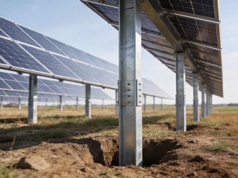
Cost & ROI Considerations for Cold-Region Solar Foundation Design
Frost protection design adds measurable incremental cost to solar foundation installation in cold regions — but the incremental cost is small relative to the frost damage remediation cost it prevents, and small relative to the total project cost. The following analysis quantifies the cost components for a representative 20 MWp utility-scale ground mount with 2,000 foundation positions in a zf = 1.2 m (AFI = 800 °C·days) continental cold climate with F3 soil:
| Frost Design Cost Component | Warm Climate Baseline | Cold Climate (zf = 1.2 m) Specification | Incremental Cost | Notes |
|---|---|---|---|---|
| Ground screw length (76 mm tube screw) | 1,400 mm (structural embedment 1,000 mm) | 1,900 mm (frost embedment 1,500 mm) | +$12–$18/screw; +$24,000–$36,000 total | 500 mm additional screw length at $24–$36/m material cost; dominant cold-region foundation cost increment |
| Screw installation productivity | 180–220 screws/day (standard rig) | 140–170 screws/day (additional torque cycles for deeper embedment) | +$0.8–$1.5/screw labor equivalent; +$1,600–$3,000 total | 15–25% productivity reduction from deeper embedment; partially offset by faster torque achievement in F3 silt versus F1 sand |
| HDPE adfreeze sleeve on screw shaft (F4 soil only) | Not required | $8–$15/screw for factory-applied HDPE sleeve in frost zone (1,200 mm length) | +$16,000–$30,000 if F4 soil confirmed | Only required in F4 silt/clay; eliminates adfreeze reduction factor for anchor resistance; allows standard helix specification |
| Geotechnical frost investigation | Standard soil investigation (no frost tests) | Grain size + Atterberg limits for CRREL frost class; AFI calculation from NOAA data; frost depth calculation memo | +$3,000–$8,000 total for investigation add-on | Most cost-effective single investment — eliminates F4 design conservatism if F1/F2 is confirmed; typical investigation adds only $1.5–$4/foundation position |
| Total frost design incremental cost (F3 soil, zf = 1.2 m) | — | — | +$44,600–$77,000 total; +$0.0022–$0.0039/Wp | Versus frost remediation cost of $800–$3,500/affected position × 15% rate × 2,000 positions = $240,000–$1,050,000 NPV over 25 years |
The cost-benefit ratio of frost-compliant design versus frost damage remediation is typically 1:5 to 1:20 — every dollar spent on frost-compliant design at installation saves $5–$20 in remediation cost over the project life. For the complete cross-climate, cross-foundation-type cost analysis that allows project developers to budget foundation costs accurately for specific cold-region locations and soil conditions, refer to the foundation cost comparison resource.
Frost Performance Comparison: Solar Foundation Types
xml
| Foundation Type | Frost Resistance Mechanism | Required Depth Adjustment | Adfreeze Risk | Cold-Climate CapEx Impact | Risk Level Without Frost Design |
|---|---|---|---|---|---|
| Driven Pile (H-pile / pipe) | Pile tip below frost line; adfreeze on shaft mitigated by HDPE sleeve or bituminous coating | Pile length = max(structural, frost) — typically +300–600 mm in cold regions | Medium — shaft adfreeze force Faf balanced by skin friction below frost line; manageable with sleeve | Medium — additional pile length cost; sleeve material; slightly reduced installation rate | High — pile shaft adfreeze can extract pile from non-frozen soil if skin friction below frost line is insufficient |
| Ground Screw | Helix plate below frost line; adfreeze on shaft above helix resisted by helix bearing below frost zone | Helix target depth = zf + 300 mm minimum; total screw length = helix depth + above-grade extension | Medium-High — shaft adfreeze on tubular screw; HDPE sleeve on shaft in frost zone recommended for F4 soil | Medium — additional screw length (dominant cost); optional HDPE sleeve; slight productivity reduction | High — helix in frost zone subject to direct bearing uplift + adfreeze; most common cold-region solar failure mode |
| Concrete Footing | Footing base below frost line (IBC 2024 mandatory); FPSF with XPS insulation as alternative | Footing total depth = zf + 200 mm minimum per IBC; 2–3× excavation volume vs warm climate in deep frost regions | Low — concrete footing dead weight (γconcrete × Vfooting = typically 5–25 kN) typically exceeds frost heave force once footing base is below frost line; adfreeze on footing perimeter is resisted by footing mass | High — deep excavation cost is the primary cold-climate concrete footing cost driver; excavation cost increases 2–4× between zf = 0.5 m and zf = 1.8 m; FPSF option reduces excavation cost but adds insulation material and QC cost | Low (if footing base is at required frost depth) — concrete footing below frost line performs reliably; primary risk is non-compliant shallow placement by installer attempting to reduce excavation cost |
| Ballasted (Surface) | No soil embedment — frost heave of ground surface under ballast blocks can displace the entire array if surface soil is frost-susceptible | No embedment adjustment possible — frost mitigation requires granular pad beneath ballast blocks (F1 material, minimum 150 mm thick) to eliminate frost-susceptible soil contact | N/A — no shaft in soil; but differential frost heave of surface between ballast positions is the primary structural concern | Low material cost but significant site preparation cost for granular frost-mitigation pad if site soil is F3/F4; site-specific assessment required | Very High — surface-placed ballast systems on frost-susceptible soil experience significant differential displacement from uneven ice lens formation; not recommended without granular mitigation pad in F3/F4 soil cold regions |
| Rock Anchor | Rock mass does not heave; adfreeze in soil overburden above rock surface is the only frost interaction; anchor head freeze-thaw cycling managed by bearing plate sealant | No depth adjustment for frost in rock (rock is non-heaving); anchor rod extends through frost-susceptible soil overburden with adfreeze check on shaft in overburden zone | Low — thin soil overburden above rock generates limited adfreeze force; rock bond capacity far exceeds adfreeze demand from typical 0.2–1.0 m soil overburden at rock anchor sites | Low frost-related incremental cost — epoxy resin grout specification for extreme alpine temperature cycling is the primary cold-climate cost addition (resin grout premium vs cement: +$8–$15/anchor) | Low — rock anchor sites are intrinsically frost-protected at the bearing level; primary risk is anchor head assembly corrosion from freeze-thaw moisture cycling if bearing plate sealant is omitted |
Rock anchoring and properly embedded concrete footings provide the highest inherent frost resistance among solar foundation types; ground screws require the most specific cold-climate design attention due to the combination of adfreeze risk and helix-in-frost-zone failure mode. For a complete cross-foundation-type engineering comparison across all structural and commercial criteria — including cold-climate performance as one of the evaluation dimensions — refer to our Solar Foundation Systems Guide.
Frost Protection Engineering Design Checklist
- Frost depth verified from climate data at 100-year return period AFI: Air Freezing Index (AFI) retrieved from NOAA Climate Data Online (or equivalent national climate database) using 30-year climate normal daily minimum temperature records at the nearest representative weather station; 100-year return period AFI calculated from annual AFI distribution (Gumbel extreme value fit); zf calculated from Modified Berggren formula using site soil thermal conductivity and latent heat parameters, or confirmed from IBC 2024 §1809.5 local frost depth map with jurisdiction verification; design frost depth documented in the foundation engineering calculations with source data reference
- Soil frost susceptibility class confirmed from grain size and Atterberg limits: Grain size analysis (ASTM D422) confirms % finer than 0.02 mm; Atterberg limits (ASTM D4318) confirm plasticity index for cohesive soils; CRREL frost susceptibility class (F1–F4) assigned per ASTM D5918; class F3 or F4 confirmation triggers: adfreeze force calculation, HDPE sleeve or coating evaluation, drainage design consideration, and use of full design τaf values from CRREL tables; class F1 confirmation allows standard embedment without adfreeze correction (significant cost saving that justifies investigation cost)
- Drainage plan confirmed for F3/F4 soil sites: Surface drainage grading specified (minimum 2% slope away from foundation zone within 3 m); subsurface drainage evaluation completed (French drain spacing calculation for target water table depth reduction); drainage outlet confirmed at project boundary or sump; granular backfill specification around pile/screw shaft in frost zone evaluated if localized frost mitigation is preferred over full embedment depth increase
- Foundation embedment depth below frost line confirmed as governing specification: Structural capacity depth Dstructural calculated from pile skin friction, screw torque correlation, or concrete dead weight; frost compliance depth Dfrost = zf + 200 mm (F1/F2 soil) or zf + 400 mm (F3/F4 soil); specified design depth Ddesign = max(Dstructural, Dfrost) documented in specifications; installer field instruction confirms that torque-based termination criteria cannot override the minimum depth requirement — installations must reach Ddesign minimum regardless of torque achievement at shallower depth
- Adfreeze force calculated and anchor resistance below frost zone verified: Faf = τaf × perimeter × zf calculated using τaf from CRREL table for soil type and shaft material; anchor resistance Qanchor,below frost (helix bearing or pile skin friction below frost zone) confirmed ≥ 1.5 × Faf; if anchor resistance insufficient: HDPE sleeve or bituminous coating specified on shaft in frost zone (reduces τaf by 60–75%), or larger-diameter bottom helix specified to increase anchor resistance
- Snow load verified for cold-climate load combinations: Ground snow load pg from ASCE 7-22 Figure 7.2-1 or local building code for project location; flat roof snow load pf = 0.7 × Ce × Ct × Is × pg for solar array at near-horizontal tilt; unbalanced snow load on fixed-tilt arrays per ASCE 7-22 §7.6; combined snow + wind load combination per ASCE 7-22 §2.3.2 (LRFD) or §2.4.1 (ASD) verified against foundation uplift and bearing capacity; tracker stow-position snow load (modules at high tilt during storm) evaluated for perimeter foundation uplift demand
- Concrete mix design confirmed for freeze-thaw exposure class: Freeze-thaw exposure class per ACI 318-19 §R26.4.1 (F0–F3) determined from site climate and concrete exposure condition; minimum total air entrainment 4.5–7.5% for Class F1–F3; w/c ≤ 0.45 for Class F2 (most cold-region solar sites); minimum f’c = 28 MPa for freeze-thaw exposed concrete; air content field test (ASTM C231 pressure method or ASTM C173 volumetric method) required at time of concrete placement — not just batch plant certification; above-grade concrete pedestal surface sealant applied after form removal (penetrating silane or siloxane: reduces surface water absorption and freeze-thaw scaling rate by 60–80%)
- Corrosion class reviewed for cold-climate moisture exposure at foundation head: Annual freeze-thaw cycling with seasonal saturation at the foundation head zone elevates corrosion risk above non-cold-climate baseline; corrosion class confirmed considering both groundwater aggressiveness (soil chemistry) and above-grade frost-zone moisture cycling (atmospheric + capillary); stainless steel or duplex galvanized + epoxy specification for anchor head hardware in areas with de-icing salt application or coastal marine aerosol in combination with freeze-thaw cycling
Failure Risks & Common Frost Design Mistakes
Underestimating Frost Depth: Using Mean Annual AFI Instead of Design Return Period
The most frequent frost depth calculation error in solar foundation design is using mean annual Air Freezing Index (AFI) data — the average over all recorded winters — rather than the design return period AFI that corresponds to the coldest winter reasonably expected over the 25–50 year project life. In continental cold climates, the 100-year return period AFI is typically 35–55% higher than the mean annual AFI — producing a frost depth that is 15–25% deeper than the mean-AFI calculation (because zf scales approximately as √AFI, the depth difference is proportionally less than the AFI difference but still significant). At zf,mean = 1.2 m: zf,100yr ≈ 1.2 × √(1.45) = 1.45 m — a 250 mm additional embedment requirement that, if ignored, leaves foundations potentially exposed to the frost zone in the coldest design winters. The engineering standard: IBC 2024 §1809.5 references locally adopted frost depth values that typically correspond to the 50-year return period AFI — using 100-year return period AFI provides additional safety margin for a 30-year project life but increases embedment cost; the minimum is the locally adopted frost depth from the AHJ, which may be based on mean or 50-year AFI depending on jurisdiction.
Ignoring Soil Moisture: Applying Non-Heaving Design to Frost-Susceptible Soil
Applying a frost design that was developed for F1 (non-susceptible) soil conditions to a project site with F3/F4 soil is the structural equivalent of designing a foundation for sand properties when the actual soil is soft clay — the structural demand (frost heave force) is fundamentally different from the assumed condition, and the resulting design is unsafe. The failure mode: a screw installation at 1.2 m embedment on a F4 silt site with zf = 1.2 m (helix exactly at the frost line, not below it) experiences σh = 200–300 kPa directly on the helix plate — Fheave,bearing = 200–300 × 0.071 m² = 14–21 kN upward — while the dead weight of the solar array tributary to that screw is 4–6 kN; net uplift = 8–17 kN progressively extracting the screw over 2–3 winter cycles until the column is visibly displaced. The required action: soil frost susceptibility classification from grain size and Atterberg limits on samples from the installation depth is the essential information that determines whether standard warm-climate embedment depth is sufficient (F1 soil) or requires frost-governed increase (F3/F4 soil).
Insufficient Drainage Design: Saturated Soil Amplifying Heave in Nominally Moderate-Risk Soil
F2 soil (low-to-medium frost susceptibility — sandy gravels, gravelly sands with 5–10% fines) that would produce only limited frost heave in well-drained, above-water-table conditions can produce F4-equivalent heave when saturation is increased by poor site drainage. Agricultural fields used for solar development frequently have field tile drainage systems installed decades earlier that are disrupted by solar construction activities (fence installation, cable trenching, access road grading) — severing existing field drains raises the local groundwater table from its pre-construction agricultural drainage level, converting a moderate-heave F2 soil into a high-heave near-saturated condition. The engineering control: pre-construction assessment of existing agricultural tile drain systems and restoration or replacement as part of the solar site civil construction scope; post-construction drainage survey before winter commissioning to confirm that all construction-disturbed drainage paths are restored or replaced.
Combining Frost and Wind Without Load Interaction Recalculation
Designing frost resistance and wind uplift resistance as independent, non-interacting load cases produces structurally non-conservative results when the two loads act simultaneously or sequentially in a damaging combination. The specific interaction that is most commonly missed: wind uplift design assumes the full dead weight of the module-racking-column assembly is available as compression resistance against uplift; frost adfreeze force acts upward, reducing the effective compression on the foundation from the assembly dead weight; in the worst case, adfreeze force Faf exceeds the assembly dead weight, converting the foundation from a compression-loaded to a tension-loaded element even without any wind loading — and then adding wind uplift on top of an already net-tension-loaded foundation produces a combined demand that exceeds the separate design checks for wind alone or frost alone. The structural requirement: the combined load case (factored wind uplift + frost adfreeze force − dead weight) must be checked explicitly as a load combination, not assumed to be bounded by the wind-only or frost-only design checks.
Frequently Asked Questions
What is frost depth and how is it calculated for a solar project?
Frost depth (zf) is the maximum depth below the ground surface to which the soil temperature drops below 0°C during the design winter season — the critical threshold below which foundation bearing elements must be placed to eliminate frost heave risk at the bearing surface. Calculation procedure: (1) obtain daily minimum temperature records for the project location from NOAA Climate Data Online (USA), Environment and Climate Change Canada, or equivalent national climate service; (2) calculate the Air Freezing Index (AFI) = sum of degree-days below 0°C for each winter season in the climate record; (3) fit the annual AFI values to an extreme value distribution (Gumbel Type I) and extract the 50-year or 100-year return period design AFI; (4) apply the Modified Berggren formula: zf = C × √(k × AFI / L) where C = correction factor (0.5–1.0 depending on surface condition), k = soil thermal conductivity (0.5–2.5 W/m·K depending on soil type and moisture), L = volumetric latent heat of soil water (40,000–60,000 kJ/m³ depending on moisture content); or use the local frost depth from IBC 2024 §1809.5 adopted frost depth maps as the minimum design value. For projects in multiple-jurisdiction states or provinces, confirm the AHJ-adopted frost depth before finalizing foundation depth specifications — locally adopted values may exceed or be less than the calculated Modified Berggren depth depending on when the local frost map was last updated.
How does frost depth affect ground screw selection for cold-region solar?
Frost depth is the primary driver of ground screw length selection in cold-region solar projects — more impactful than structural capacity in most F3/F4 soil environments at standard wind speeds. The selection process: (1) calculate required helix depth Dhelix = max(structural capacity depth, frost compliance depth); frost compliance depth = zf + 300 mm minimum in F3/F4 soil; (2) total screw length = Dhelix + above-grade extension to column base (typically 200–600 mm depending on array type and ground clearance); (3) screw shaft diameter: the frost-governed longer screw length requires checking that the shaft slenderness (L/d ratio) remains within the manufacturer’s buckling resistance limit — longer screws in soft soil above frost depth may require larger shaft diameter to maintain adequate compressive stability during installation. Example: zf = 1.4 m, F3 silty clay, structural capacity achieved at 1.1 m: Dhelix = max(1.1, 1.7) = 1.7 m frost-governed; total screw length = 1.7 + 0.4 m above-grade = 2.1 m; a 2.1 m screw is a non-standard length requiring special order from most manufacturers with 4–8 week lead time — cold-region ground screw procurement must account for non-standard lengths driven by frost depth.
Can insulation replace deep embedment for frost protection in solar foundations?
Insulation can reduce — but in most solar foundation configurations cannot eliminate — the embedment depth required for frost protection. Frost-Protected Shallow Foundation (FPSF) technology per ASCE 32-01 allows concrete footing embedment reduction of 400–800 mm when XPS insulation is placed horizontally at 300–500 mm depth extending 600–1,200 mm outward from the footing perimeter — the insulation intercepts the heat flow path from warm soil below to the frost surface above, maintaining soil temperature at the footing bearing level above 0°C. FPSF is practical for concrete footings (a block element with sufficient plan area to support the insulation geometry) but geometrically impractical for pile and screw foundations (a linear shaft element with no plan area to support horizontal insulation placement). For concrete footings in cold regions: FPSF can reduce excavation depth by 400–600 mm at AFI = 1,000–2,000 °C·days, with XPS insulation cost typically less than the concrete and excavation cost saved; engineering calculation per ASCE 32-01 is required to confirm the insulation geometry providing the target frost depth reduction. For pile and screw foundations: deep embedment (helix below frost line) is the only frost compliance strategy; insulation is not a viable alternative.
What is adfreeze and how does it affect solar pile and screw foundations?
Adfreeze is the adhesive and frictional bond that develops between frozen soil and a metallic pile or screw shaft surface in the frost zone — it acts as an upward jacking force on the shaft when seasonal ground heave occurs, and as a downward drag force during thaw settlement (negative adfreeze or frost-pull). In solar foundation engineering, the upward adfreeze force during winter heaving is the critical design condition: Faf = τaf × π × d × zf where τaf = 50–250 kPa (soil-specific) and d = shaft diameter. For a 76 mm shaft in F4 frozen silt at τaf = 180 kPa and zf = 1.5 m: Faf = 180 × π × 0.076 × 1.5 = 64.5 kN upward — this force must be resisted by the helix or pile tip anchor capacity below the frost zone with FS ≥ 1.5. Two adfreeze mitigation approaches: (1) smooth HDPE or bituminous coating on shaft in frost zone reduces τaf by 60–75% (most cost-effective); (2) deeper embedment increases anchor resistance below frost zone to balance Faf at standard τaf. Neither approach is inherently superior — the optimal choice depends on soil F-class, zf, and the relative cost of additional screw length vs sleeve material at the specific project scale.
Do rock anchor foundations need frost design in cold climates?
Rock anchor foundations require significantly less frost design attention than soil-based foundations but are not entirely frost-exempt. The critical distinction: intact rock does not undergo frost heave (no capillary pore structure for ice lens growth, negligible water content in the rock matrix) — the bearing element of a rock anchor is frost-protected by the inherent properties of rock regardless of frost depth. The frost-relevant design elements for rock anchors are: (1) soil overburden above rock (if present): adfreeze on the anchor shaft within frost-susceptible soil overburden above the rock surface must be checked as for pile foundations — typically not a critical condition because the overburden is thin (0.2–1.0 m) and rock bond capacity far exceeds the adfreeze demand from thin overburden; (2) anchor head assembly: freeze-thaw cycling at the bearing plate-rock surface interface can trap water that jacks the bearing plate upward — bearing plate perimeter sealant prevents this; (3) grout column thermal cycling in alpine environments: cement grout in extreme temperature range sites (ΔT > 60°C annual) benefits from replacement with epoxy resin grout for improved elongation capacity under differential thermal strain. Cold-region rock anchor design is governed by corrosion protection of the anchor head assembly in the freeze-thaw moisture zone — not by structural frost depth compliance.
How do I determine if my solar project site requires frost depth design?
Frost depth design is required for any solar project site that experiences below-freezing soil temperatures at foundation bearing depth during any winter season. The determination process: (1) confirm project latitude and elevation (sites above 40°N or above 1,500 m elevation in any latitude are highly likely to require frost design); (2) retrieve site AFI from NOAA or equivalent national climate service — any site with AFI > 50 °C·days (1–2 weeks of mild freezing per year) requires frost depth check; (3) confirm soil type at foundation bearing depth — F1 soil (clean gravel, coarse sand) requires frost depth check for embedment compliance only (no heave force design); F3/F4 soil (silt, clay) requires full frost heave and adfreeze force design; (4) check local building code minimum frost depth — IBC 2024 §1809.5 or locally adopted amendment; AHJ plan review will enforce the code minimum regardless of calculated zf. Sites with AFI = 0 (confirmed by climate data: mean daily minimum temperature never drops below 0°C in any month) are frost-exempt and require no frost design — primarily tropical locations below 23°N at low elevation.
What geotechnical data is needed to complete a frost protection design for solar foundations?
Complete frost protection design for a solar foundation project requires six geotechnical and climate data inputs: (1) Daily minimum temperature records: 30-year climate normals from the nearest representative weather station (NOAA, Environment Canada, or equivalent) — required to calculate AFI and design frost depth; (2) Grain size analysis (ASTM D422): % finer than 0.02 mm at the foundation embedment depth — determines CRREL frost susceptibility class (F1–F4); (3) Atterberg limits (ASTM D4318): liquid limit and plasticity index for cohesive soils — confirms clay versus silt classification within F3/F4 and refines τaf selection; (4) Natural moisture content (ASTM D2216): in-situ water content at frost zone depth — determines available in-situ water for ice lens growth; (5) Groundwater depth: observed in open borings or piezometers — controls capillary supply to frost front; (6) Soil thermal conductivity (ASTM D5334 or published CRREL tables): required input to Modified Berggren frost depth formula; estimated from soil type and moisture content if direct measurement is not available. The complete site investigation scope and sampling protocol that generates all six inputs as part of a standard geotechnical investigation program — without requiring any additional mobilization or testing beyond the standard solar foundation investigation scope — is detailed in the soil investigation report resource.
Related Engineering Topics
Frost protection design interacts with and depends on several parallel engineering design streams. The following resources provide the complementary structural engineering framework for cold-region solar projects:
- Seismic design — Cold-region solar sites in seismically active zones (Alaska, Pacific Northwest, Japan, New Zealand) require simultaneous frost protection and seismic design — two independent structural demands that must both be satisfied at the same foundation element; the combined design process must confirm that the frost-governed embedment depth (typically deeper than structural demand) also satisfies the seismic site class determination (Vs30 averaged over the frost-governed embedment depth, not the structural depth) and that the Ω0-amplified seismic connection force does not exceed the anchor head connection capacity specified for the frost design
- Wind load calculation — Wind load is the co-governing structural demand alongside frost heave in most cold-region solar foundation design situations — high-latitude sites experience both extreme frost depth and elevated wind speeds (reduced surface roughness over snow-covered terrain, absence of vegetation wind breaks in winter); the combined wind uplift + frost adfreeze load case must be evaluated explicitly; the wind load calculation resource provides the ASCE 7-22 velocity pressure and uplift coefficient calculations required to determine the wind demand component of the combined frost-wind load combination
- Corrosion protection — Cold-climate solar foundations face a specific corrosion challenge that is distinct from warm-climate corrosion: freeze-thaw cycling at the foundation head zone creates repeated wet-dry-freeze cycles that are more corrosively damaging than either permanently wet or permanently dry conditions; the corrosion protection resource provides the complete protection class specification for metallic foundations in freeze-thaw aggressive environments, including the coating systems (HDG, duplex, stainless) that maintain protective integrity through the 25-year design life of thermal cycling in cold regions
Prepare for project-specific review
Use this guide to organize the site, load, system and compliance inputs that a product supplier, licensed engineer, installer or local authority will need. PVRack does not provide project-specific engineering approval or supplier quotations.