
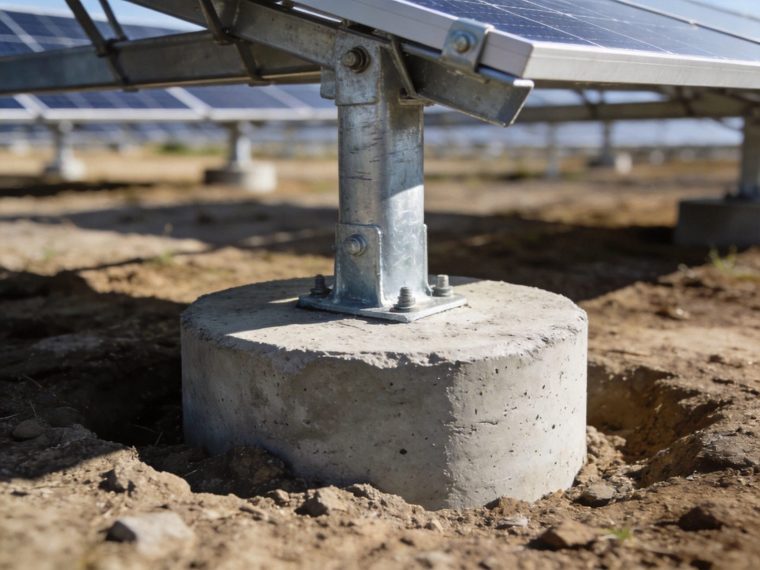
Concrete foundations remain one of the most established solar foundation systems used in large-scale PV installations — delivering unmatched structural mass, bearing capacity, and resistance to uplift in soil conditions where driven piles, ground screws, or ballasted systems cannot achieve the required structural performance. The reinforced concrete foundation transfers all solar mounting loads — wind uplift, wind lateral force, snow, seismic, and dead load — through a combination of dead weight, soil bearing at the base, and passive soil resistance against the footing perimeter, achieving structural capacities that no lightweight foundation type can replicate at equivalent plan dimensions. Concrete foundations are the structural choice when soil conditions demand deep bearing, when wind or seismic loads exceed the capacity of alternative foundation types, or when the 30–50-year design life requirement of a permanent utility-scale installation demands a foundation system with a proven long-term structural performance record. For a complete breakdown of all available foundation types, selection criteria by soil condition, climate, and project scale, refer to our Solar Foundation Systems Guide — the authoritative engineering reference for all solar foundation selection decisions.
The commercial trade-off of concrete foundations — higher initial capital cost and slower installation compared to pile-driven or ground screw alternatives — is justified by their structural superiority in challenging soil and load conditions, and by a total lifecycle cost profile that, in high-demand environments, frequently outperforms faster but structurally lighter alternatives over the 25–30-year project life.
Technical Snapshot: Concrete Foundation Key Parameters for Solar Mounting
| Parameter | Typical Value / Range | Governing Condition | Engineering Note |
|---|---|---|---|
| Embedment / Footing Depth | 1.2–2.5 m; up to 3.0 m in very soft soil or high frost-depth regions | Soil bearing capacity; frost depth; uplift demand; lateral shear | Must extend minimum 200–300 mm below local frost depth; deeper footing in soft clay to mobilize adequate bearing area; footing depth governs concrete volume and cost more than any other parameter |
| Concrete Strength Class | C25/30 (fck = 25 MPa) minimum for structural footings; C30/37 (fck = 30 MPa) preferred in aggressive soil (sulfate, chloride); C20/25 minimum for mass concrete unreinforced applications | Structural demand; soil aggressiveness; frost exposure | ACI 318-19 §19.2: minimum f’c = 3,000 psi (21 MPa) for structural concrete; f’c = 4,000 psi (28 MPa) for foundation elements in moderate to high sulfate exposure; EN 206:2013 exposure class XA1–XA3 governs concrete mix in aggressive soil |
| Reinforcement Coverage | 75 mm minimum concrete cover to rebar in soil-exposed faces; 50 mm cover to rebar in interior faces; 40 mm cover above-grade faces in non-aggressive environment | ACI 318-19 §20.6.1; EN 1992-1-1 §4.4 | Cover below minimum specification is the leading cause of rebar corrosion in concrete foundations — cover spacers must be used during rebar placement to guarantee minimum cover; cover verification is a mandatory QA inspection item at each pour |
| Typical Footing Plan Dimension | 400×400 mm to 800×800 mm for single-column footings; 600×1,200 mm for two-column strip footings; governed by allowable bearing pressure and overturning moment from wind or seismic | Net allowable soil bearing capacity qa (kPa) × footing area ≥ factored column load | In soft clay (qa = 50–75 kPa), footing plan dimensions grow rapidly — a 25 kN column load requires minimum 600×600 mm footing at qa = 70 kPa; in medium sand (qa = 150–200 kPa), same load requires only 400×400 mm |
| Anchor Bolt Grade & Diameter | M20–M36 ASTM F1554 Grade 55 (common US specification); M20–M30 Grade 8.8 with anchor plate (European); embedment length 200–500 mm depending on bolt diameter and design tension demand | Wind uplift + overturning moment at anchor bolt group | Anchor bolt breakout capacity (ACI 318-19 Chapter 17 / EN 1992-4) often governs over bolt tensile strength — concrete cone breakout at the anchor bolt group must be verified with edge distance and group effect factors applied |
| Typical CapEx Level | $35–$85/foundation at small utility scale (1–10 MWp); $28–$65/foundation at large utility scale (≥ 50 MWp); $0.018–$0.035/Wp total foundation cost including excavation, concrete, rebar, and anchor bolts | Project scale (mob cost amortization); concrete supply distance; soil excavation difficulty | Concrete supply distance is the dominant cost variable for remote utility-scale projects — concrete transport beyond 60 km significantly increases cost per m³ and may make driven pile or ground screw foundations more economical regardless of structural preference |
| Design Service Life | 30–50 years structural; potentially 50–75 years in non-aggressive soil with adequate cover and proper concrete mix | Concrete cover adequacy; rebar corrosion protection; freeze-thaw exposure; soil aggressiveness | Concrete foundation structural service life exceeds the 25-year solar module warranty by 5–25+ years, making concrete the preferred foundation where land re-use for future solar installations is planned |
What Is a Concrete Foundation in Solar Mounting Projects?
Structural Concept of Reinforced Concrete Base
A reinforced concrete foundation for solar mounting is a cast-in-place or precast structural element that transfers all loads from the solar mounting column above — wind uplift, wind lateral force, snow, seismic, and dead load — into the surrounding soil through a combination of three resistance mechanisms: (1) Direct bearing: the footing base area bears against the soil beneath, transferring compressive load through contact pressure; the bearing pressure distribution is approximately trapezoidal under eccentric loading (overturning moment from wind) and must not exceed the allowable bearing pressure qa of the soil at any point on the footing base; (2) Dead weight uplift resistance: the mass of the concrete footing (typically 2,400 kg/m³ for standard reinforced concrete) provides gravitational resistance to wind uplift — the footing weight must exceed the net factored uplift force (with safety factor ≥ 1.5–2.0) to prevent footing displacement; (3) Passive soil resistance: the footing perimeter surfaces push against the surrounding soil under lateral loading (wind lateral force or seismic base shear), developing passive earth pressure resistance proportional to the footing depth and soil passive pressure coefficient Kp. The understanding of how each resistance mechanism activates under different load combinations — and how they interact when multiple loads act simultaneously — is governed by the solar load transfer principles that define the load path from panel to soil through the concrete foundation system.
Core Components and Reinforcement Structure
A reinforced concrete solar mounting foundation comprises six structural components working as an integrated system: (1) Excavation void: the soil cavity shaped to receive the footing, with walls vertical or battered depending on soil stability; excavation bottom must be at or below design bearing depth, on undisturbed soil free of loose material; (2) Lean concrete blinding layer: 75–100 mm thin unreinforced concrete (C15/20 or f’c = 2,000 psi) poured at the excavation bottom to provide a clean, level bearing surface for rebar placement — prevents contamination of lower rebar with soil and water; (3) Reinforcement cage: deformed steel bars (rebar) arranged as a three-dimensional cage — bottom mat (typically 2–4 bars each way, diameter 12–16 mm) resisting bending in the footing slab under bearing pressure; vertical bars (4–8 bars per column face, diameter 12–20 mm) resisting tension from overturning moment at the column-to-footing interface; horizontal ties at 150–200 mm spacing providing confinement and shear resistance; (4) Anchor bolt assembly: cast-in anchor bolts (ASTM F1554 Grade 55 or equivalent), held in template frame during pour, that receive the solar mounting column base plate after concrete curing; anchor bolt position tolerance ±3–5 mm is critical for racking system base plate alignment; (5) Concrete mass: structural concrete at specified strength class, mixed to specified w/c ratio, poured around the rebar cage and consolidated by internal vibration; (6) Backfill: compacted granular fill placed around footing perimeter after curing to design density, providing the soil overburden pressure that contributes to dead-weight uplift resistance and passive lateral resistance. Proper site-specific soil investigation data — including bearing capacity, groundwater table, and soil aggressiveness — that governs footing dimension selection and concrete mix design comes from the soil and geotechnical analysis report.
When Engineers Prefer Concrete Foundations for Solar Mounting
Structural engineers specify concrete foundations over pile-driven or ground screw alternatives in five defining project conditions: (1) Very soft or weak soil (SPT N < 5; qa < 50 kPa): driven piles in very soft clay require extreme embedment depths (sometimes >4 m) that are uneconomical; a concrete pad foundation spreads the column load over a larger bearing area, reducing bearing pressure to within the soil’s allowable bearing capacity at a practical footing depth; (2) Soil with obstructions preventing pile driving: buried concrete, dense cobble layers, old foundations, or near-surface rock that prevents pile penetration to design depth; concrete foundation excavation and pour works around obstructions that defeat pile driving; (3) Very high lateral or seismic demand (SDC D–F): concrete foundations achieve lateral resistance through massive passive pressure on large perimeter surfaces — a capability that driven piles (limited by pile section EI and soil kh) and ground screws (limited by helix bearing area) cannot match at extreme lateral loads; (4) Permanent installations requiring 40–50-year structural life: utility-scale projects where the land will be re-used for a second solar installation after the first decommissions benefit from concrete foundations that remain structurally intact for a second racking system without replacement; (5) Sites where concrete supply logistics are acceptable: concrete foundation economics depend critically on concrete supply distance — within 30–40 km of a ready-mix plant, concrete foundations are cost-competitive; beyond 60–80 km, logistics costs favor concrete-free alternatives.
Engineering Principles of Concrete Foundations for Solar Mounting
Axial Compression and Soil Bearing Capacity
The axial compression load at a solar mounting concrete foundation consists of the panel dead load, structural dead load (racking hardware), and any gravity live load (snow). Under ASCE 7-22 LRFD governing gravity combination (1.2D + 1.6S + 1.0L), the factored axial load at each foundation is typically 15–40 kN for standard utility-scale ground mount at 2.5–3.0 m post spacing and moderate-to-heavy snow load. The required footing plan area for bearing capacity: Areq = Pu / (φ × qnet) where qnet = net allowable bearing pressure (gross bearing capacity minus overburden pressure at footing depth); φ = 0.75 (ASD-to-LRFD conversion from geotechnical report, or direct LRFD capacity factor). In soft clay with qnet = 60 kPa: Areq = 35/60 = 0.58 m² → 762×762 mm footing minimum plan dimension. The bearing capacity check must additionally include eccentric loading correction: when overturning moment M from wind acts at the footing level, the effective bearing area is reduced to Aeff = (B − 2e) × L where e = M/P = eccentricity; peak bearing pressure at the windward edge must remain ≤ qult/FSbearing.
Lateral Stability Through Mass and Passive Resistance
Lateral load resistance in a concrete foundation is provided by two mechanisms acting simultaneously: (1) Base friction: horizontal shear resistance at the footing base = µ × N (where µ = coefficient of friction between concrete and soil ≈ 0.4–0.6; N = net vertical force at base including footing dead weight minus uplift); (2) Passive soil pressure: the footing side face develops passive earth pressure resistance = 0.5 × Kp × γ × D² × B per unit width (where Kp = (1+sinφ)/(1−sinφ) for Rankine passive; D = footing depth; B = footing width). For a 600×600×1,500 mm deep footing in medium sand (φ = 32°, γ = 18 kN/m³): Kp = 3.25; passive resistance per face = 0.5 × 3.25 × 18 × 1.5² × 0.6 = 39.5 kN — substantially more than the lateral wind force on a standard solar mounting column (typically 2–8 kN at 2.5 m column height). The mass of the concrete footing (0.6 × 0.6 × 1.5 m × 24 kN/m³ = 12.96 kN self-weight) adds to the base friction resistance. Concrete foundations achieve lateral resistance through sheer mass and geometry — a structural mechanism that requires no soil-steel interaction quality (unlike pile skin friction or screw bearing) and is therefore the most reliable lateral resistance mechanism in variable or poorly characterized soil conditions.
Uplift Resistance by Dead Weight and Anchor Embedment
Wind uplift resistance in a concrete foundation combines two sources: the dead weight of the concrete footing itself, and the soil overburden above the footing bearing area. Net uplift resistance = Wconcrete + Wsoil overburden − factored net uplift force ≥ 0 (with safety factor FS ≥ 1.5 for ASD, or φ ≥ 0.60 for LRFD). For a 600×600×1,500 mm footing at 1.5 m embedment with 300 mm footing above bearing: Wconcrete = 12.96 kN; Wsoil = (1.2 m overburden) × 0.6 × 0.6 × 18 = 7.78 kN; total dead weight resistance = 20.74 kN. At a corner pile in Vult = 130 mph coastal site, net factored uplift = 18–25 kN — requiring FS check: 20.74/22 = 0.94 — marginal; footing must be enlarged or deepened to increase dead weight resistance. This calculation illustrates why concrete foundation sizing for solar mounting in high-wind environments is driven primarily by uplift resistance (requiring mass), not bearing capacity (requiring area) — the opposite of the intuitive expectation. For a comprehensive understanding of all foundation type options within this engineering context, review the complete solar foundation guide.
Soil–Concrete Interaction Mechanism
The soil-concrete interaction in a solar mounting footing operates through three contact zones: (1) Bearing contact at base: concrete-to-soil bearing pressure transfer; the bearing pressure distribution is linear-elastic for footings on cohesive soil, but may be non-linear in sands due to stress-dependent stiffness; the footing must be rigid enough (adequate thickness) to maintain approximately uniform bearing pressure distribution — ACI 318-19 §13.3 governs minimum footing thickness as a function of column load and concrete strength; (2) Adhesion and friction at footing base perimeter: in cohesive soil, adhesion between concrete and clay at the footing base perimeter resists uplift by approximately ca × Aperimeter (where ca = adhesion = 0.5 × su for cast-in-place concrete against undisturbed clay); this adhesion component is typically neglected in design for conservatism; (3) Passive pressure at footing sides: as described above — the full passive pressure capacity requires mobilization displacement of approximately 0.5–2% of footing depth, meaning the footing must move horizontally 7–30 mm before full passive resistance is mobilized; the allowable lateral deflection at the footing head (pile top) for solar mounting systems (typically ≤ 10–15 mm) must be verified to confirm whether full passive resistance is available at the design serviceability limit.
Structural Anatomy & Cross-Section Breakdown
Excavation and Footing Dimensions
Footing plan dimensions are determined by the governing limit state: bearing capacity (requires minimum plan area), overturning stability (requires minimum plan dimension to limit eccentricity e ≤ B/6 for no-tension bearing condition), and uplift dead weight (requires minimum concrete volume). The design sequence: (1) establish design loads from structural analysis (Paxial, Moverturning, Hlateral); (2) determine required plan area from bearing capacity: Areq = Pu/qa; (3) check overturning: e = M/P ≤ B/6 — if e > B/6, the footing base lifts at one edge and bearing pressure analysis requires special treatment (cracked section analysis); (4) check uplift: Wconcrete + Wsoil ≥ Tu,net × FS — if insufficient, increase footing depth or plan dimension; (5) check lateral: Hu ≤ (base friction + passive resistance)/FS. Footing depth must include the local frost depth as a minimum: bottom of footing ≥ frost depth + 200 mm. In northern Canada (frost depth 1.8–2.4 m), this requirement alone governs footing depth to 2.0–2.6 m — requiring significantly more concrete volume than the structural demand requires, and making concrete foundations expensive in deep-frost markets.
Reinforcement Cage Layout
Reinforcement cage design for a solar mounting isolated footing follows ACI 318-19 Chapter 13 (Two-Way Slabs) and Chapter 26 (Construction Documents): bottom mat reinforcement sized for bending moment in the footing plate Mu = qu × Lc²/2 (where Lc = distance from critical section at column face to footing edge); top mat reinforcement to resist uplift bending when net uplift exceeds dead weight (the footing slab bends upward as anchor bolts pull up against downward bearing pressure); vertical dowels (4–8 bars, diameter 12–20 mm) extending from bottom mat upward to connect the footing to the column pedestal or anchor bolt assembly; horizontal ties at 150–200 mm spacing for confinement and minimum reinforcement ratio. Minimum reinforcement ratio per ACI 318-19 §13.3.2.1: ρmin = 0.0018 for grade 60 (fy = 420 MPa) deformed bars — for a 600 mm wide × 300 mm thick footing slab: As,min = 0.0018 × 600 × 300 = 324 mm² = 2-#13 bars (2×129 mm² = 258 mm² — use 3-#13 at 200 mm spacing). The rebar placement must achieve the minimum concrete cover to all bar surfaces — cover spacers placed on the blinding layer before rebar placement are mandatory, not optional. Inadequate concrete cover over rebar at soil-exposed surfaces is the root cause of premature rebar corrosion that limits concrete foundation service life in aggressive environments — the complete corrosion protection specification for concrete foundation rebar and anchor bolts is in the foundation corrosion protection methods resource.
Anchor Bolts and Base Plate Integration
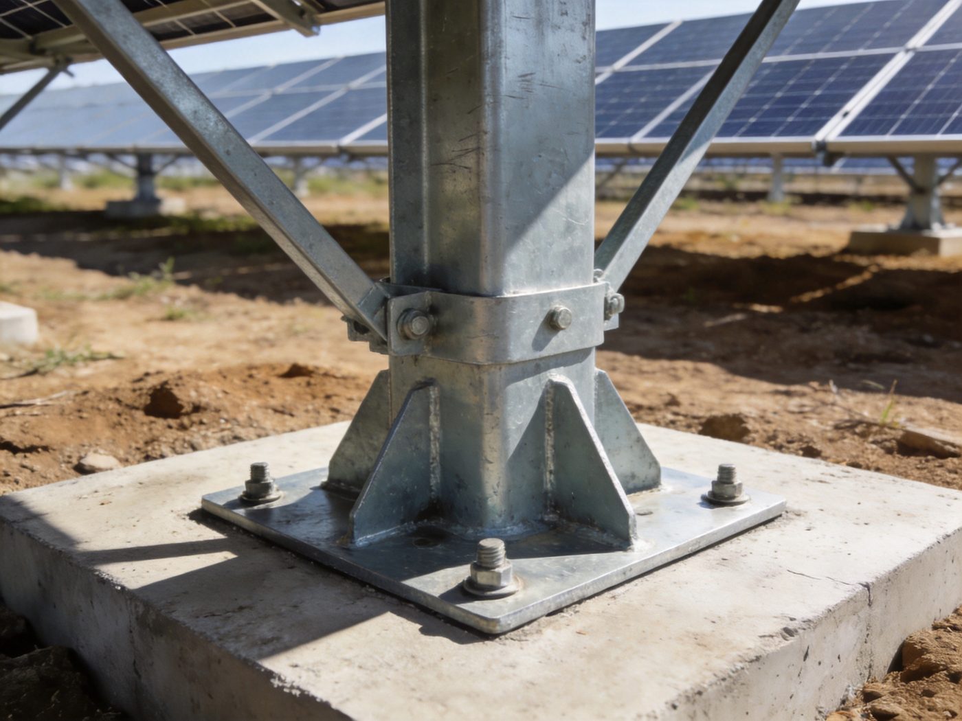
Anchor bolt placement in a concrete solar mounting foundation is the most position-critical operation in the entire construction sequence — anchor bolts cast at incorrect position or alignment cannot be corrected after concrete hardens without expensive coring or cutting. Standard anchor bolt specification for solar mounting concrete foundations: ASTM F1554 Grade 55 (Fy = 380 MPa, Fu = 520 MPa) for standard applications; ASTM F1554 Grade 105 for high-tensile demand applications at high-wind or high-seismic sites; bolt diameter M20–M30 (3/4″–1-1/4″) for typical solar mounting column bases; anchor embedment length 10db–20db to develop full tensile capacity without concrete cone breakout. Concrete cone breakout capacity per ACI 318-19 §17.6.2 governs the anchor bolt group design: Ncb = kc × √f’c × hef^1.5 (for a single anchor); group breakout requires application of group effect factor ψec,N and edge distance factor ψed,N. At M24 bolts with 300 mm embedment in C30 concrete: Ncb,single = 10 × √30 × 300^1.5 = 10 × 5.48 × 5196 = 284,754 N = 285 kN — significantly above the bolt steel tensile capacity of 0.75 × Fu × Ab = 0.75 × 520 × 452 = 176 kN, confirming that steel capacity, not concrete breakout, governs at this embedment — design is adequate.
Concrete Strength Class and Cover Thickness
Concrete strength class and cover thickness are co-specified design decisions that together determine the service life of the foundation against corrosion-induced rebar deterioration. For solar mounting foundations in standard inland soil (non-aggressive, sulfate class S0): C25/30 (f’c = 3,500 psi, fck = 25 MPa) with 75 mm cover to rebar at soil-exposed faces; for sulfate-aggressive soil (class S1–S2, SO₄ > 0.1%): C30/37 (fck = 30 MPa) with sulfate-resistant cement (Type V per ASTM C150 or SRPC per BS 4027), w/c ≤ 0.45, and 75 mm cover; for chloride-contaminated soil (near-coastal groundwater): C35/45 (fck = 35 MPa), w/c ≤ 0.40, 90 mm cover, or supplementary corrosion protection (epoxy-coated rebar, stainless rebar, or cathodic protection) at C4–C5 soil sites.
Installation Workflow
Phase 1 — Site Survey, Pre-Construction Engineering, and Excavation
Pre-construction engineering for concrete foundations requires four completed deliverables before excavation begins: (1) validated geotechnical investigation report with soil profile, bearing capacity by depth, frost depth, groundwater table, and soil aggressiveness classification; (2) structural engineer-stamped footing design drawings specifying plan dimensions, depth, concrete strength class, rebar schedule, cover requirements, and anchor bolt details; (3) concrete mix design approved for exposure class and strength requirement; (4) anchor bolt templates fabricated to survey-verified column grid dimensions. Excavation: machine excavation (backhoe for standard cohesive soil; hydraulic excavator with rock breaker attachment for rocky subgrade) to design bearing depth; bottom of excavation on undisturbed, competent soil — remove all loose soil and standing water before lean concrete placement. Verify bearing capacity by visual inspection (qualified geotechnical engineer or inspector) and confirm with field bearing capacity test if soft zones encountered. The foundation selection guide establishes the decision criteria for determining when concrete foundations are the appropriate selection for a given site condition, and provides the pre-construction engineering checklist required before excavation mobilization.
Phase 2 — Rebar Placement, Anchor Bolt Setting, and Concrete Pouring
After lean concrete blinding layer achieves initial set (minimum 4 hours before rebar placement): (1) Cover spacers placed on blinding layer at 600 mm maximum spacing — 75 mm height for soil-exposed bottom mat; verify spacer type is concrete or plastic (not steel) to prevent corrosion path to rebar; (2) Bottom mat rebar placed on spacers, bar positions and spacing checked against drawings; (3) Vertical bars and ties assembled into three-dimensional cage; ties at specified spacing, secured with wire ties at alternating intersections; (4) Anchor bolt template installed: survey-positioned to ±3 mm plan tolerance; template secured to rebar cage at top; anchor bolts plumb ± 0.5° from vertical — any angular deviation translates to base plate non-planarity at the mounted column position; (5) Pre-pour inspection: independent structural inspector verifies rebar size, spacing, cover, and anchor bolt position before concrete placement approval; (6) Concrete placement: concrete placed in lifts ≤ 500 mm, consolidated with internal vibrator at 450 mm maximum spacing; vibrator must not contact anchor bolts or rebar (vibrator contact can displace anchors from template position); surface struck off level with footing top elevation. Ambient temperature at time of pour must be between 5°C and 35°C for standard concrete mix — low-temperature concrete admixtures (accelerators, heated water) required below 5°C; high-temperature measures (chilled water, shade) required above 35°C.
Phase 3 — Curing, Backfill, and Structural Inspection
Concrete curing is the most frequently compromised phase in solar concrete foundation construction — schedule pressure to begin racking installation causes premature stripping and loading that permanently reduces concrete strength and durability. Required curing standards: moist curing for minimum 7 days (standard OPC concrete) to achieve 70% of specified 28-day strength; 3 days minimum with Type III (rapid-hardening) cement if schedule requires; curing blankets or plastic sheeting sealed at edges for the entire curing period; no direct solar exposure of uncured concrete surface without shade or membrane curing compound. Concrete does not achieve full specified strength until 28 days after pour — anchor bolt tightening and racking installation must wait until concrete reaches minimum 75% of f’c (typically 10–14 days for standard OPC concrete at 20°C); premature loading before this threshold can fracture the concrete cone around anchor bolts irreparably. Post-curing structural inspection: anchor bolt position survey (±5 mm tolerance from design position); concrete surface quality inspection (voids, cold joints, inadequate cover); compressive strength verification by cylinder test (minimum 2 cylinders per 10 m³ or per footing pour, tested at 7 and 28 days).
Worked Screening Example: Why Loads Must Precede Dimensions
This simplified example demonstrates the first screening checks; it is not a construction design. Assume one circular concrete pier receives service compression P = 85 kN, uplift T = 24 kN and overturning moment M = 18 kN·m. The preliminary geometry is 1.0 m diameter by 1.5 m deep, with normal-weight concrete at approximately 24 kN/m³ and an allowable soil bearing pressure of 150 kPa.
| Screening check | Calculation | Result and design implication |
|---|---|---|
| Base area | A = πD²/4 = 0.785 m² | Area available for the preliminary bearing check |
| Average bearing | q = P/A = 85/0.785 ≈ 108 kPa | Below 150 kPa before moment is included; this alone does not prove adequacy |
| Eccentricity | e = M/P = 18/85 ≈ 0.212 m | Greater than the circular kern radius D/8 = 0.125 m, so the simple full-contact assumption fails and the base needs resizing or detailed soil-pressure analysis |
| Concrete self-weight | W = π(0.5²)(1.5)(24) ≈ 28 kN | Only a small margin above the 24 kN uplift demand before required factors and other load combinations; weight alone is not a robust uplift design |
| Next checks | Soil overburden, anchor steel, concrete breakout, sliding, settlement, frost, reinforcement and durability | The preliminary 1.0 m pier should not be issued for construction from the two simple checks above |
The useful result of a worked example is sometimes a rejection: a foundation can pass average bearing while failing eccentricity or uplift margin. Final sizing must use factored load combinations, project geotechnical parameters, the adopted concrete code and a licensed engineer's sealed calculations.
Concrete Foundation Design Input Sheet
- Column reactions for every governing compression, uplift, shear and moment combination.
- Allowable and ultimate bearing values, lateral soil parameters, groundwater, settlement criteria and frost depth.
- Concrete strength and exposure class, reinforcement grade, cover, anchor-bolt layout and base-plate dimensions.
- Construction tolerances, drainage, curing plan, test requirements and permitted field corrections.
Performance Analysis
Wind Load Resistance
Concrete foundations provide wind load resistance through three simultaneously active mechanisms — dead weight (uplift), passive earth pressure (lateral), and base bearing capacity (overturning) — that combine to provide structural margin under all ASCE 7-22 governing LRFD wind load combinations. The critical wind load performance check for concrete solar foundations is overturning stability at the footing base: the overturning moment MOT = Hwind × (hcolumn + Dfooting/2) must be resisted by the stabilizing moment Mstab = (Wconcrete + Wsoil) × B/2, producing eccentricity e = MOT/Ptotal ≤ B/6 (no-tension condition at footing base). At Vult = 150 mph with Hwind = 8 kN per column and column height 1.8 m above grade, Dfooting = 1.5 m: MOT = 8 × (1.8 + 0.75) = 20.4 kN·m; Ptotal = 13 kN (dead) + 12 kN (concrete weight) + 8 kN (soil overburden) = 33 kN; e = 20.4/33 = 0.62 m. For a 1,200 mm square footing: B/6 = 0.20 m — e = 0.62 m > B/6, cracked section condition; footing must be enlarged to B = 6e = 6 × 0.62 = 3.72 m — clearly impractical; the design solution is to increase footing depth (increasing stabilizing dead weight) or to rely on anchor bolt tension capacity for the overturning moment, distributing the OTM through the anchor bolt group as tension + compression couple. The wind pressure calculation framework that generates the Hwind input driving this overturning analysis is in the wind load calculation standards resource.
Frost and Freeze-Thaw Durability
Concrete foundations in cold climates must satisfy two independent frost-related structural requirements: (1) Foundation bearing below frost depth: footing base must be at or below the local frost penetration depth to prevent frost heave — seasonal freezing of saturated cohesive soil beneath a footing can generate uplift pressures of 50–200 kPa, capable of lifting the footing and displacing the solar mounting column by 30–80 mm over a winter-spring frost cycle; (2) Concrete durability under freeze-thaw cycling: concrete in the upper 500 mm of footing (alternately wet and frozen) must resist freeze-thaw deterioration — ACI 318-19 Table 19.3.3 specifies that concrete exposed to freezing and thawing in a moist condition (Exposure Class F1: moderate; F2: severe) requires f’c ≥ 31 MPa (F1) or f’c ≥ 35 MPa (F2) with minimum 6% total air content for F1 and 6% for F2; air entrainment is mandatory — non-air-entrained concrete in freeze-thaw exposure will surface-scale and lose cover concrete within 5–10 frost cycles, exposing reinforcement to corrosion. The site-specific frost depth determination and the frost heave risk classification for different soil types and drainage conditions that determine whether the minimum footing depth is governed by frost or by bearing capacity are developed in the frost protection design requirements resource.
Long-Term Settlement Risk
Long-term settlement of concrete solar mounting foundations occurs through two mechanisms with different time scales: (1) Immediate elastic settlement: occurs at load application; typically 5–15 mm in medium cohesive soil, 3–8 mm in medium-dense sand; calculated from Boussinesq elastic theory using soil elastic modulus from pressuremeter or laboratory consolidation test; immediate settlement is completed within days of loading and does not present differential settlement risk between adjacent foundations installed simultaneously; (2) Primary consolidation settlement: in normally consolidated or lightly overconsolidated clay, sustained dead load causes gradual volume reduction as porewater drains — time scale for 90% primary consolidation: t90 = 0.848 × Hdr² / cv (where Hdr = drainage path; cv = coefficient of consolidation from laboratory oedometer test); in a 3 m clay layer with double drainage and cv = 2 × 10⁻³ cm²/s: t90 = 0.848 × 150² / 0.002 = 9,540,000 s = 110 days. Differential settlement between adjacent foundations of >25 mm over the 25-year project life can misalign tracker drive mechanisms, distort panel row geometry, and cause progressive structural overloading of the racking system — differential settlement verification is a mandatory part of the foundation design for soft clay sites.
Advantages & Limitations
Structural and Commercial Advantages
- Highest uplift and lateral resistance of all non-deep foundation types: concrete mass directly provides dead weight uplift resistance and passive pressure lateral resistance without relying on soil-pile interface quality; the resistance mechanisms are directly calculable from concrete density and footing geometry — no soil-pile interaction variability
- Widest soil applicability: concrete spread footings work in very soft clay (N < 5), organic soil, fill, and disturbed ground where pile driving achieves inadequate embedment and ground screws fail to develop torque; by spreading load over a larger bearing area, concrete footings bring the bearing pressure within the allowable range of almost any soil type
- 30–50-year structural service life: correctly designed and constructed reinforced concrete foundations outlast the solar project’s 25-year life, providing foundation re-use capability for second-generation installations on the same land without foundation replacement cost
- Proven performance in seismic SDC D–F: concrete foundations for CBF or moment-frame solar mounting structures in high seismic zones achieve the large passive pressure resistance required for seismic base shear transfer; the capacity is code-verifiable (ACI 318-19, IBC 2024) and accepted by structural engineers and building officials in all major seismic markets
- No pile driving noise or vibration: concrete foundation installation (excavation + pour) produces significantly less construction noise and ground vibration than impact pile driving — critical in urban-adjacent solar installations, rooftop commercial installations, and noise-sensitive permitting jurisdictions
Structural and Commercial Limitations
- Curing time adds 10–14 days to critical path: the concrete curing period before racking installation — minimum 10–14 days for 75% strength at 20°C, up to 21 days in cold weather — is a hard schedule constraint that impact-driven pile foundations eliminate entirely; on a 200 MWp project with 40,000 foundations poured in 2-week batches, the curing schedule is the binding constraint on foundation-to-racking handover and directly affects project financing
- High CapEx per foundation: at $35–$85 per foundation versus $28–$45 for a driven pile, concrete foundations cost 25–90% more per foundation unit — the premium widens at remote sites where concrete logistics add $5–$30/m³ transport cost; at 10,000 foundations per 50 MWp project, the premium is $70,000–$400,000 versus equivalent pile driven specification
- Not reversible at end of project life: concrete foundations cannot be extracted without significant excavation and concrete crushing cost; in jurisdictions with mandatory site restoration requirements at end of solar project life, concrete removal cost ($15–$35/foundation) adds $150,000–$350,000 per 50 MWp project to decommissioning cost
- Concrete supply chain dependency: ready-mix concrete logistics (60 km maximum economic haul distance, perishable 90-minute workability window, dependent on weather above 5°C for standard mix) create supply chain constraints that driven pile foundations eliminate; remote sites and cold-weather construction windows make concrete foundations logistically challenging
- Slow installation rate: excavation + pour + cure cycle limits production to 40–80 foundations per crew-day versus 200–500 piles per rig-day for driven foundations — the installation rate constraint extends project schedule and increases site overhead and financing cost per day of schedule extension
Best Application Scenarios
Weak or Unstable Soil Sites
Concrete spread footings are the structural solution of choice for utility-scale solar on very soft clay, loose fill, organic soil, or sites with shallow bearing strata underlain by soft compressible layers. When SPT N-values in the upper 1.5–2.0 m are below 5, driven piles of standard solar mounting sections cannot develop adequate skin friction for uplift resistance at economical embedment depths, and ground screws cannot develop installation torque correlating to helical bearing capacity. A concrete footing with plan dimensions sized for the allowable bearing capacity of the weak soil — and with dead weight sized for wind uplift resistance — provides a structurally reliable solution that does not depend on pile-soil interface friction or screw helical bearing, both of which are unreliable in very soft or variable soil.
High Wind Coastal Areas
In high-wind coastal regions — Southeastern US coast, Gulf of Mexico shoreline, Caribbean, typhoon-track Pacific Asia — concrete foundations provide the maximum dead weight uplift resistance and passive pressure lateral resistance that extreme wind events demand. At Vult ≥ 150 mph and Exposure D conditions, net uplift forces per column can reach 30–60 kN at array perimeter positions — forces that require either deep driven pile embedment with verified pull-out capacity or concrete foundations with dead weight sufficient to resist the uplift without relying on soil-concrete adhesion. Coastal sites are also ISO C4–C5 corrosion environments where the long-term reliability of steel pile corrosion protection is a concern; concrete foundations with adequate cover and air-entrained concrete provide corrosion protection through concrete alkalinity rather than zinc coating, eliminating the zinc depletion failure mode that affects steel foundations at coastal sites.
Permanent Utility-Scale Installations
For utility-scale solar installations on land held for long-term development — where a second or third solar installation generation is planned after the first project’s 25-year life — concrete foundations that remain structurally intact for 40–50 years provide a capital efficiency benefit across the land’s full energy production life. The marginal additional cost of a concrete foundation over a pile driven alternative ($15–$40/foundation) amortized over two solar project cycles (50 years) is $0.30–$0.80/foundation per year — negligible against the $2,500–$5,000/foundation cost of concrete foundation replacement between projects. The re-use criterion makes concrete foundations economically superior to any removable foundation type for multi-cycle solar land development strategies.
Cost & ROI Considerations
Concrete foundation cost analysis for solar mounting must account for five cost components: concrete material and delivery, excavation, rebar and anchor bolt hardware, forming (if required), and curing and inspection. At utility scale (50 MWp, approximately 10,000 foundations), typical cost breakdown for a US Gulf Coast site (soft clay, N = 5–15; Vult = 140 mph; concrete supply within 40 km):
| Cost Component | Unit Cost | Total at 10,000 Foundations | $/Wp |
|---|---|---|---|
| Ready-mix concrete (0.25 m³ per foundation, C30/37, air-entrained, $145/m³ delivered) | $36.25/foundation | $362,500 | $0.0073 |
| Excavation (machine excavation 0.4 m³ per foundation at $12/m³) | $4.80/foundation | $48,000 | $0.0010 |
| Rebar (12 kg per foundation at $1.20/kg fabricated) | $14.40/foundation | $144,000 | $0.0029 |
| Anchor bolts (4× M24 F1554 Gr55 HDG per foundation at $8.50/bolt) | $34.00/foundation | $340,000 | $0.0068 |
| Labor (excavation, rebar, pour, inspection at $22/foundation) | $22.00/foundation | $220,000 | $0.0044 |
| Geotechnical investigation & QA testing | $8.50/foundation | $85,000 | $0.0017 |
| Total concrete foundation cost | $120/foundation | $1,199,500 | $0.024/Wp |
At $0.024/Wp, concrete foundations are 25–55% more expensive than pile driven foundations ($0.011–$0.019/Wp) at equal scale. The premium is justified when: (a) soil conditions require concrete for structural adequacy (soft clay N < 8 with high uplift demand); (b) the site is in a noise-restricted zone prohibiting pile driving; (c) the land development plan includes a second-generation solar installation that will re-use the foundations. The premium is not justified in standard soil conditions with no structural driver for concrete — pile driven foundations should be the default in those conditions. For a side-by-side cost analysis with pile driven foundations including installation speed and lifecycle cost dimensions, see the foundation cost comparison analysis; for the specific structural and commercial trade-off between the two types in standard utility-scale ground mount applications, see the pile vs concrete comparison.
Comparative Engineering Matrix
| Criterion | Concrete Foundation | Pile Driven | Ground Screw | Ballasted |
|---|---|---|---|---|
| CapEx ($/Wp) | $0.018–$0.035 ❌ Highest | $0.011–$0.019 ✅ | $0.015–$0.028 | $0.008–$0.018 ✅ Lowest |
| Installation Speed | 40–80/day ❌ Slowest | 200–500/day ✅ Fastest | 150–350/day ✅ | 100–200/day |
| Soil Flexibility | ✅ Very High — works in soft clay, fill, organic | Medium — N = 5–40 optimal | Medium — torque-dependent | ❌ Limited — needs firm bearing surface |
| Wind Uplift Resistance | ✅ Very High — mass-based | ✅ High — skin friction | Medium — helical bearing | Medium — self-weight only |
| Lateral Load Resistance | ✅ Very High — passive pressure | ✅ High — EI × kh | Medium | ❌ Low |
| Freeze-Thaw Durability | ✅ High — air-entrained concrete | ✅ High — steel below frost | ✅ High | ❌ Poor — uplift in frost heave soil |
| Site Reversibility | ❌ Low — removal costly | Medium — extractable | ✅ High — fully reversible | ✅ High — removable |
| Schedule Impact (Curing) | ❌ 10–21 days cure delay | ✅ None | ✅ None | ✅ None |
| Design Life | ✅ 30–50 years | 25–40 years (coating dependent) | 20–35 years | 25–30 years |
Concrete foundations lead on structural performance, soil applicability, and design life — and trail on cost, installation speed, and site reversibility. The choice between concrete and faster alternatives depends on whether the structural performance advantage is required by the site conditions and load demands. For a broader overview of all foundation options, refer back to our Solar Foundation Systems Guide for the complete foundation selection framework across all project types, soil conditions, and climate zones.
Engineering Design Checklist
- Soil investigation report completed and validated: minimum one boring or CPT per 2 acres; bearing capacity qa by depth confirmed; groundwater table depth recorded; soil aggressiveness classification (sulfate, chloride, pH) documented for concrete mix design selection
- Frost depth confirmed for project location: local frost penetration depth obtained from ASCE 7-22 Figure C11.4-2 or national climatic data; footing design depth verified to extend minimum 200 mm below frost depth at all foundation positions
- Concrete strength class verified against exposure class: sulfate exposure class per ACI 318-19 Table 19.3.2; freeze-thaw exposure class per Table 19.3.3; minimum f’c and w/c ratio confirmed; air entrainment specified for F1/F2 exposure
- Reinforcement design approved by structural engineer of record: bottom mat sizing for bearing pressure bending; vertical bar sizing for overturning moment at column interface; minimum cover spacers specified (75 mm at soil-exposed faces); rebar material specification (ASTM A615 Grade 60 standard; epoxy-coated or stainless for C4–C5 soil)
- Anchor bolt design completed including concrete breakout check: ACI 318-19 Chapter 17 concrete cone breakout capacity verified ≥ factored anchor tension demand; edge distance and group effect factors applied; anchor bolt embedment length and grade specified on stamped drawings
- Wind load calculations completed per ASCE 7-22: Vult, exposure category, height coefficients, and CN by array position confirmed; governing uplift and lateral forces per foundation position calculated; overturning eccentricity e ≤ B/6 verified (or cracked section analysis performed)
- Curing plan specified in construction documents: minimum curing duration (7 days moist curing standard OPC); minimum concrete strength before loading (75% of f’c); cold-weather and hot-weather contingency measures specified; cylinder testing frequency and acceptance criteria defined
- Post-installation QA plan in place: anchor bolt position survey (±5 mm tolerance) within 48 hours of pour; concrete strength verification by cylinder test at 7 and 28 days; visual inspection of formed surfaces for voids and cold joints before backfill
Failure Risks & Common Engineering Mistakes
Insufficient Curing Time Before Loading
Premature anchor bolt tightening or racking column installation before concrete achieves 75% of specified strength is the most common construction-phase failure mechanism in solar concrete foundation projects. When the column base plate is torqued to the anchor bolt at early age (3–5 days at standard OPC concrete), the local bearing stress at the nut-to-concrete interface and the tensile stress in the concrete cone below the anchor head exceed the early-age concrete tensile capacity — micro-cracking in the concrete cone reduces the anchor’s long-term pull-out capacity below the code-required design value. The failure is invisible at installation and manifests only under the first major wind event, when anchor bolt breakout or concrete cone fracture occurs at below-design loads. Project schedule pressure is the root cause — the engineering control is a strict minimum concrete age specification in the construction documents with independent inspector verification before loading authorization.
Improper Rebar Placement and Inadequate Cover
Rebar placement errors — incorrect bar spacing, missing bars, insufficient concrete cover — are systematically underinspected on solar foundation projects because the foundations are numerous, small, and repetitive, creating an inspection fatigue risk. The structural consequence of inadequate concrete cover (measured cover < 75 mm at soil-exposed faces) is accelerated rebar corrosion that initiates within 5–15 years in aggressive soil: corrosion products expand to 3× the parent steel volume, splitting the concrete cover and exposing the rebar to direct soil contact; the corroded rebar section loses tensile capacity proportional to section loss, eventually reducing the foundation’s uplift and overturning moment resistance below the code-required minimum. Cover verification with a calibrated cover meter at 10% sample of footings before backfill is the minimum acceptable QA measure.
Differential Settlement Between Adjacent Foundations
Differential settlement — unequal long-term settlement between adjacent foundations — is more structurally damaging than uniform settlement in solar mounting systems. A uniform 20 mm settlement of all foundations in a tracker row moves the entire row downward without structural distortion; a differential settlement of 20 mm between two adjacent foundations on the same tracker distorts the tracker torque tube by 20 mm over the 6–10 m inter-post span — potentially jamming the drive mechanism, overstressing the torque tube, and causing drive motor overload or failure. Differential settlement risk is highest in layered soil profiles where soft clay lenses occur at varying depths across the project footprint — one foundation may be bearing on medium sand (elastic settlement 5 mm) while an adjacent foundation is on soft clay (consolidation settlement 25 mm). The geotechnical investigation density required to identify these soil layer variations before foundation design is specified in the soil investigation requirements.
Poor Corrosion Protection in Aggressive Soil
Concrete alkalinity (pH 12–13 in fresh concrete) passivates rebar against corrosion — but this passivation breaks down when: (a) concrete carbonation reduces pH below 9 in the cover zone over 15–30 years in CO₂-rich soil environments; (b) chloride penetration from saline groundwater reaches the rebar surface and destroys the passive film at [Cl⁻] > 0.4% by cement weight; (c) sulfate attack on the cement matrix (SO₄ > 0.1% in soil or groundwater) weakens the cover concrete, reducing effective cover to rebar. All three mechanisms are soil-environment driven and must be characterized in the geotechnical investigation to specify the correct concrete mix, cover thickness, and supplementary protection (epoxy-coated rebar in chloride environments; sulfate-resistant cement in SO₄-aggressive soil).
Frequently Asked Questions
What concrete strength is required for solar mounting foundations?
Minimum structural concrete strength for solar mounting foundations per ACI 318-19 is f’c = 3,000 psi (21 MPa) for all structural concrete members; f’c = 3,500 psi (24 MPa) for foundations exposed to moderate sulfate (Exposure Class S1); f’c = 4,000 psi (28 MPa) for foundations in severe sulfate environments (Class S2) or moderate-to-severe freezing and thawing (Class F1–F2). In practice, most structural engineers specify C25/30 (fck = 25 MPa, f’c ≈ 3,600 psi) as the standard specification for solar mounting concrete foundations — providing margin above the ACI minimum and meeting most exposure class requirements in standard soil. Air entrainment (5–7% air content for 19 mm maximum aggregate size in F1 exposure; 6–8% for F2) is mandatory in freeze-thaw exposed concrete and must be specified in the concrete mix design.
How deep should a concrete solar mounting foundation be?
The minimum foundation depth is the greater of: (a) the local frost depth plus 200–300 mm (to prevent frost heave); (b) the depth at which the soil bearing capacity qa exceeds the design bearing pressure (Pu/Afooting); (c) the embedment depth required for anchor bolt breakout capacity per ACI 318-19 Chapter 17. In the continental United States, frost depth ranges from 0 (southern Florida, Hawaii) to 2.4 m (northern Minnesota, Montana), making frost depth the governing depth requirement in most northern projects. In non-frost regions, bearing capacity governs — typically 1.0–1.5 m in medium soil. Always design to site-specific soil conditions; applying a uniform 1.5 m “standard” depth without soil investigation can produce inadequate bearing or uplift capacity at soft soil sites, or unnecessary excess cost at competent soil sites.
Can concrete foundations be used on sloped terrain?
Yes — concrete foundations are one of the most adaptable foundation types for sloped terrain because each footing is individually formed and poured to a specific height that accommodates the slope-induced grade change between adjacent foundations. Unlike pile-driven foundations (where pile head elevation tolerance of ±20 mm limits slope accommodation to the racking adjustment range) or ballasted foundations (which require essentially flat terrain for stability), concrete foundations can be sized and formed at any elevation, providing a structurally level base plate surface at any terrain slope. On steep terrain (>20% grade), concrete footings with variable column heights at the high and low side of each table are the standard engineering solution — often more economical than terrain-following racking with elaborate adjustable pile height systems.
When is it better to use pile driven foundations instead of concrete?
Pile driven foundations are structurally and commercially preferable to concrete foundations in four conditions: (1) project scale ≥ 5 MWp in standard soil (SPT N = 10–35) where installation speed advantage (200–500 piles/day vs 40–80 concrete pours/day) produces a schedule saving that exceeds the concrete cost premium; (2) remote sites where ready-mix concrete logistics (supply distance > 60 km) make concrete cost non-competitive; (3) projects on agricultural land or in jurisdictions requiring full site restoration at project end, where pile extraction cost is lower than concrete demolition cost; (4) projects with tight construction schedules where the 10–21-day concrete curing delay cannot be accommodated in the racking installation program. Concrete foundations are preferable when soil is too soft for pile skin friction capacity, when driving is obstructed by shallow rock or cobble, or when seismic or wind demands exceed pile lateral capacity.
What causes anchor bolt failure in solar concrete foundations, and how is it prevented?
Anchor bolt failures in solar concrete foundations occur through three mechanisms: (1) Concrete cone breakout: tension pulls a cone of concrete from the footing — prevented by adequate embedment depth (≥ 10db) and edge distance (≥ 6db) with ACI 318-19 Chapter 17 verification; (2) Bolt corrosion: zinc coating depletion at bolt-to-concrete interface in aggressive soil — prevented by epoxy-coated or hot-dip galvanized anchor bolts with adequate concrete cover; (3) Premature loading: early-age concrete fracture at the anchor bearing surface from loading before 75% of f’c achieved — prevented by strict minimum curing time specification and independent inspector loading authorization. The most effective prevention measure for all three mechanisms combined is correct embedment depth specification with code-compliant edge distances, adequate concrete strength class for the exposure, and enforced minimum curing period before bolt loading — three items that are directly verifiable with the soil geotechnical evaluation data and a site QA inspection program.
What is the installed cost of concrete foundations for utility-scale solar?
Installed cost for concrete solar mounting foundations at utility scale (≥ 10 MWp) in standard US conditions ranges from $0.018–$0.035/Wp total, or $65–$125 per foundation including excavation, concrete, rebar, anchor bolts, labor, and quality testing. Cost drivers: concrete supply distance (adds $0.003–$0.008/Wp beyond 50 km transport); soil conditions (soft clay requiring deeper footings and larger plan areas adds 30–50% concrete volume); anchor bolt specification (stainless or Grade 105 bolts add $8–$15 per foundation); and frost depth (each additional 500 mm of footing depth adds approximately $12–$18 per foundation in concrete and excavation). At the higher end of this range ($0.035/Wp), concrete foundations cost nearly 3× the lower bound for driven pile foundations ($0.011/Wp) — making the structural justification for concrete critical to project economics.
Prepare for project-specific review
Use this guide to organize the site, load, system and compliance inputs that a product supplier, licensed engineer, installer or local authority will need. PVRack does not provide project-specific engineering approval or supplier quotations.
Are Ground Screws Cheaper Than Concrete? Cost & Sourcing Verdict
Verdict: In most workable soils, ground screws and driven piles are cheaper and faster than cast-in-place concrete because they need no excavation, formwork or curing time — concrete wins only where soils are too weak or variable to drive into. The indicative cost/engineering comparison below helps you decide before requesting a quote.
| Factor | Concrete Foundation | Ground Screw / Driven Pile |
|---|---|---|
| Relative installed cost (indicative) | Higher | Lower in workable soil |
| Install time | Days (excavate, pour, cure) | Same-day, no cure |
| Site disturbance | High (spoil, formwork) | Low (minimal spoil) |
| Best for | Weak / expansive / contaminated soil | Standard drivable soil, frost (screws) |
| Removable / reusable | No | Yes (screws) |
Independent-use note: PVRack does not provide product-specific design, supplier quotations, sealed drawings or approval guarantees. Confirm project requirements with the relevant manufacturer, qualified local professionals and authority having jurisdiction.