
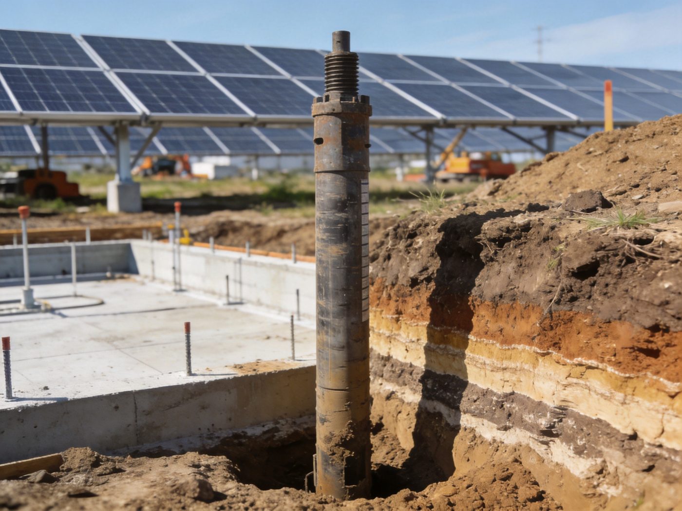
Proper soil and geotechnical evaluation is the engineering prerequisite for all solar foundation systems — the structural calculations that determine pile embedment depth, screw torque requirements, concrete footing dimensions, and rock anchor bond length are only as reliable as the geotechnical data they are based on. Before selecting pile, screw, concrete, or rock anchoring solutions, structural engineers must characterize the soil profile: bearing capacity by depth, shear strength parameters, consolidation behavior, groundwater table, frost depth, soil aggressiveness, and seismic site class — all of which govern not just whether a foundation type is structurally viable, but whether it will maintain its design capacity over a 25–50-year solar project life. Geotechnical risk is the leading cause of solar foundation cost overruns, installation delays, and post-construction structural performance deficiencies in utility-scale solar development — sites with inadequate pre-construction geotechnical investigation routinely require foundation redesign, pile re-driving, or concrete supplementation after installation begins, at costs of $50,000–$500,000+ per project. For an overview of all solar foundation types and their governing selection criteria, visit our Solar Foundation Systems Guide.
The scope of geotechnical investigation required for solar foundations is project-specific — a 500 kWp rooftop ballasted system requires only a building structural review, while a 200 MWp utility-scale ground mount on variable alluvial soil requires systematic borings or CPT soundings at 3–5 acre intervals, laboratory consolidation testing, and seismic site class determination across the full project footprint. The universal principle: geotechnical investigation cost (typically $15,000–$80,000 for a 10–50 MWp project) is the highest-return engineering expenditure in solar foundation design — it eliminates the structural uncertainty that, if unresolved, generates change orders 10–50× larger than the investigation cost during construction.
Technical Snapshot: Geotechnical Investigation Scope for Solar Foundation Design
| Parameter | Typical Range / Value | Governing Foundation Decision | Engineering Note |
|---|---|---|---|
| Soil Bearing Capacity (qa) | Soft clay: 40–75 kPa; Medium clay / loose sand: 75–150 kPa; Stiff clay / medium sand: 150–300 kPa; Dense sand / gravel: 300–600 kPa; Rock: 2,000–50,000 kPa | Concrete footing plan dimension; pile end bearing capacity; screw torque-to-capacity correlation | qa is the single most impactful geotechnical parameter for concrete footing sizing — footing plan area scales inversely with qa; a 3× difference in qa between assumed (design) and actual (field) values produces a 3× error in footing area and a 1.7× error in footing plan dimension |
| SPT N-Value (blows/300 mm) | Very soft: N < 4; Soft: N 4–10; Medium: N 10–30; Stiff/Dense: N 30–50; Hard/Very Dense: N > 50 | Pile drivability; ground screw torque range; liquefaction susceptibility at seismic sites | SPT N is the most widely used field parameter for solar foundation design in North America and Asia; correlates to pile skin friction (Meyerhof: fs = N/50 tsf for sand), screw Kt torque factor, and soil bearing capacity; N > 50 (refusal) in the upper 3 m indicates rock or dense gravel that defeats screw installation and requires pre-drilling or foundation type change |
| Undrained Shear Strength (su) | Very soft clay: su < 12.5 kPa; Soft: 12.5–25 kPa; Firm: 25–50 kPa; Stiff: 50–100 kPa; Very stiff: 100–200 kPa; Hard: >200 kPa | Short-term pile skin friction; concrete bearing capacity in undrained loading; screw helix bearing in cohesive soil | su < 25 kPa (soft clay) is the most structurally challenging condition for solar foundations — pile skin friction is low, requiring long embedment; screw torque correlation has high variability; concrete footings require large plan area; installation equipment (pile hammer, screw rig) may cause excessive ground disturbance that remolds the clay and temporarily reduces su by 30–50% |
| Internal Friction Angle (φ’) | Loose sand: φ’ = 28–32°; Medium-dense sand: φ’ = 32–36°; Dense sand/gravel: φ’ = 36–42°; Gravel: φ’ = 38–45° | Long-term pile skin friction; passive earth pressure for lateral resistance; screw helix bearing in cohesionless soil | φ’ governs long-term drained capacity in cohesionless soil — the foundation type that performs best in dense cohesionless soil (φ’ > 36°) is the driven pile, which mobilizes both end bearing (qb = Nq × σ’v, where Nq increases strongly with φ’) and high skin friction; ground screws also perform well due to high torque correlation in dense sand |
| Consolidation Parameters (Cc, cv) | Cc = 0.2–0.5 for medium-high plasticity clay; cv = 1×10⁻³–5×10⁻² cm²/s depending on clay type and stress history | Long-term settlement magnitude and rate under concrete footing dead load | Settlement governs concrete footing design on compressible clay sites — total primary consolidation settlement S = Cc × H / (1+e0) × log(σ’f/σ’0); differential settlement between adjacent footings > 25 mm over 25 years can misalign tracker drives and overstress racking connections; normally consolidated clay (OCR ≈ 1) has highest settlement risk |
| Groundwater Table Depth | 0–5 m in humid coastal and alluvial plains; >10 m in arid and semi-arid inland sites; artesian (positive pore pressure above ground level) at some coastal sites | Effective stress for bearing capacity; pile buoyancy reduction; corrosion protection class; dewatering requirement for concrete excavation | High groundwater (within 0.5 m of surface) increases uplift risk on concrete footings (reduces effective bearing pressure by buoyancy), increases corrosion risk on all metallic foundation elements, requires dewatering for concrete excavation (significant cost addition), and may trigger special corrosion class specification (Class II or III) for ground screws and rock anchors |
| Frost Penetration Depth | 0 m (tropical); 0.3–0.8 m (mild temperate); 0.8–1.5 m (continental temperate); 1.5–2.5 m (sub-arctic); >2.5 m (arctic) | Minimum foundation embedment depth; frost heave risk for shallow foundations; concrete mix design (freeze-thaw exposure class) | Frost depth is a mandatory design input that sets the minimum embedment depth regardless of structural capacity — a ground screw achieving design torque at 0.8 m embedment in a 1.2 m frost depth region must still be driven to 1.4 m (frost depth + 200 mm) to place the helix below the frost zone, consuming more screw length than the structural demand requires and increasing material cost |
| Seismic Site Class | Class A (hard rock): Vs30 > 1,500 m/s; Class B (rock): 760–1,500 m/s; Class C (very dense soil): 360–760 m/s; Class D (stiff soil): 180–360 m/s; Class E (soft clay): Vs30 < 180 m/s or su < 25 kPa in top 30 m | Seismic site amplification factors Fa and Fv; SDS and SD1 design spectral accelerations; SDC determination; liquefaction potential | Site Class E (soft clay) produces the highest seismic amplification — Fa = 2.5–3.5 at short periods; combined with high SS spectral acceleration, SDS on Site Class E can be 2–3× higher than on Site Class C at the same location, potentially elevating SDC from B to D and triggering Ω0 amplified connection design requirements that do not apply at the lower SDC |
Why Soil Investigation Is Critical for Solar Foundation Projects
Role of Geotechnical Reports in Foundation Design
The geotechnical investigation report is the engineering document that converts an uncharacterized piece of land into a structurally definable foundation design environment — providing the soil parameters (bearing capacity, shear strength, consolidation, groundwater, frost depth, seismic site class) that are the required inputs to every foundation structural calculation. Without a project-specific geotechnical report, the structural engineer must either (a) assume conservative default soil parameters from code tables — which typically results in over-designed, over-cost foundations; or (b) assume optimistic parameters to achieve competitive foundation pricing — which results in under-designed foundations with risk of post-construction structural distress. Neither outcome is acceptable for a 25-year investment with lender-required structural certification. A complete geotechnical report for a solar project provides: soil boring logs with SPT N-values by depth at representative locations; laboratory test results (grain size, Atterberg limits, consolidation, UCS if rock is present); groundwater table observations; frost depth from regional frost index data cross-checked with site-specific data; geotechnical engineer’s written recommendations for foundation type selection, bearing capacity by depth, and pile/screw/anchor capacity parameters for structural calculations. The geotechnical report is also the document that allows the structural engineer to calculate, verify, and certify the load transfer principles governing how each foundation type distributes solar system loads into the soil at that specific site — without this data, load transfer verification cannot be performed to a professional standard.
Soil Bearing Capacity and Structural Safety: The Foundation of Foundation Design
Allowable soil bearing capacity qa is the single most consequential geotechnical parameter for solar foundation design — it governs the plan dimensions of concrete footings (Afooting ≥ Pcolumn/qa), the pile end bearing contribution (qb = Nq × σ’v at pile tip), and the quality check on ground screw torque correlation (confirmed design capacity must produce torque within the rig’s capability range at the specified embedment depth). The relationship between bearing capacity and foundation sizing is inverse and non-linear: in soft clay (qa = 50 kPa), a 25 kN column load requires Afooting = 0.50 m² (710×710 mm); in medium-dense sand (qa = 200 kPa), the same load requires Afooting = 0.125 m² (355×355 mm) — a 4× reduction in footing plan area from a 4× improvement in bearing capacity, with a roughly 2.5× reduction in footing concrete volume. The structural safety requirement for bearing capacity is expressed as: qfactored = Pu/Aeff ≤ φ × qult (LRFD) or qapplied ≤ qult/FS (ASD, FS = 2.5–3.0 for solar foundations per ASCE 7-22 and IBC 2024 §1806.3). Bearing capacity failure — plastic shear failure in the soil beneath the footing that produces sudden large settlement — is the ultimate structural limit state; serviceability limit state (excessive settlement) typically governs concrete footing design before bearing capacity failure is reached.
Impact on Foundation Type Selection
The geotechnical investigation outcome directly determines which foundation type is structurally viable at a project site — and often eliminates one or more foundation types from consideration before the commercial comparison begins. Five geotechnical finding-to-decision links: (1) SPT N > 50 (refusal) at < 1.5 m depth: rock or dense gravel defeats ground screw installation; driven pile requires rock-breaking tip; rock anchoring or concrete with rock excavation are the viable options; (2) su < 20 kPa in upper 2 m (very soft clay): ground screw torque correlation unreliable; driven pile requires very long embedment for adequate skin friction; concrete footing requires large plan area and may require deep embedment for adequate dead weight uplift resistance; pile solution at deeper competent layer often most economical; (3) Groundwater at surface: concrete footing excavation requires dewatering; corrosion class II or III mandatory for all metallic foundations; (4) Frost depth > 1.5 m: all penetrating foundations must extend to frost depth + 200 mm regardless of structural capacity achievement; concrete footing volume increases with frost depth; (5) Liquefiable sand layer (N < 15 in SDC D–F): all foundation embedment must extend below the liquefiable layer to competent non-liquefiable soil; this may add 2–5 m to required embedment depth, significantly increasing all foundation costs at the affected site. The structured decision framework that integrates geotechnical findings with wind, seismic, frost, and commercial constraints to produce a defensible foundation type recommendation is in the foundation selection guide.
Soil Classification & Engineering Properties for Solar Foundation Design
Cohesive vs Non-Cohesive Soils: Fundamental Behavioral Distinction
The primary geotechnical classification for solar foundation design is the distinction between cohesive soils (clays and silts — fine-grained, plasticity-controlled behavior) and non-cohesive soils (sands and gravels — coarse-grained, friction-controlled behavior). This distinction governs almost every aspect of foundation design: cohesive soils are characterized by undrained shear strength su (the resistance to shear failure under rapid loading, before porewater can drain) and drained cohesion c’ + friction angle φ’ (the long-term drained resistance); non-cohesive soils are characterized by friction angle φ’ alone (cohesion ≈ 0 in clean sand and gravel). The practical design implication: cohesive soil foundation performance must be checked under both undrained (short-term, construction period) and drained (long-term, service life) conditions — the governing condition depends on loading rate and drainage path length; non-cohesive foundation performance is governed by the drained condition only, because sand and gravel drain freely under any practical loading rate. Foundation installations in soft cohesive soil also require sensitivity to construction-induced disturbance: pile driving and screw installation in soft clay remold the clay in the immediate vicinity of the pile or screw shaft, temporarily reducing su to the remolded shear strength (typically 20–50% of the intact su); the soil recovers (set-up effect) over days to weeks as excess porewater pressure dissipates and thixotropic strength recovery occurs — capacity immediately after installation in soft clay is therefore lower than the long-term design capacity, which must be confirmed by re-testing after the set-up period.
Clay Behavior: Settlement, Consolidation, and Long-Term Load Response
Clay soils present three engineering challenges unique to cohesive soils that must be explicitly addressed in solar foundation design: (1) Primary consolidation settlement: sustained dead load from solar racking and foundation elements compresses the clay as excess porewater pressure generated at load application gradually dissipates; settlement S = Cc × H/(1+e0) × log(σ’f/σ’0) where Cc = compression index, H = clay layer thickness, e0 = initial void ratio, σ’f/σ’0 = stress ratio after/before loading; in a 4 m normally consolidated clay layer (Cc = 0.35, e0 = 0.95) with 50 kPa stress increase from a concrete footing: S = 0.35 × 4/(1+0.95) × log(150/100) = 0.718 × 0.176 = 126 mm total settlement — potentially occurring over 5–15 years in low-permeability clay; (2) Secondary compression (creep): long-term volume change under constant effective stress, continuing after primary consolidation is complete; rate Cα = 0.005–0.020 × Cc for most inorganic clays; cumulative secondary settlement over 25 years can add 15–40 mm to primary consolidation settlement in high-plasticity clay; (3) Differential settlement: variation in settlement between adjacent foundations due to natural variability in clay layer thickness and consistency across the project footprint; differential settlement of > 25 mm between adjacent pile or screw positions can impose secondary stresses in the racking system and misalign tracker drive mechanisms; the risk of differential settlement — not the absolute settlement magnitude — typically governs the serviceability limit state check for concrete and pile foundations on compressible clay.
Sandy Soil: Friction Characteristics and Drained Performance
Sand and gravel soils — the most favorable foundation conditions for solar mounting foundations of all types — provide their structural resistance through friction and interlocking at grain contacts, governed by friction angle φ’ and relative density Dr. Dense sand and gravel (Dr > 65%, SPT N = 30–50+) provide bearing capacity of 200–600 kPa, pile skin friction of 50–120 kPa, and ground screw torque responses of 3,000–10,000 N·m at 1.5 m embedment — sufficient for all but the most extreme wind uplift demands without requiring extended embedment depths. Loose to medium-dense sand (Dr = 35–65%, N = 10–30) provides moderate performance: bearing capacity 75–200 kPa, pile skin friction 20–60 kPa, adequate screw torque in most utility-scale applications. The critical concern in sand and gravel soils at seismic sites is liquefaction: loose saturated sand (N < 15, Dr < 50%) in SDC D–F is susceptible to earthquake-induced liquefaction — a temporary loss of bearing capacity and shear strength when seismic pore pressure buildup causes the soil to behave as a liquid; all foundation elements must extend through the liquefiable layer to competent soil below. For sites where shallow rock is encountered beneath the sand layer, the transition from sand to rock presents an opportunity for significantly enhanced foundation performance using rock anchoring solutions that can mobilize rock bond strength far exceeding the overlying sand’s capacity.
Rock Layer Identification: Depth, Quality, and Foundation Implications
Rock layer identification in the soil profile — from surface outcrop to deeply buried bedrock — requires different investigation approaches depending on depth: shallow rock (0–3 m depth) is identified by SPT refusal (N > 50) in standard borings, confirmed by rock core sampling; deeper rock (>3 m) requires rotary core drilling with rock coring equipment (HQ or NQ diameter core barrel); rock quality is classified by Rock Mass Rating (RMR) from core recovery percentage (RQD), joint spacing and roughness, and UCS testing of core specimens. The engineering significance of rock depth for solar foundations: (1) 0–0.5 m depth (surface outcrop or shallow rock): eliminates ground screws and driven piles as viable options; rock anchoring is the only viable penetrating foundation type; concrete with rock excavation is costly but feasible if rock is weak (UCS < 30 MPa); (2) 0.5–2.0 m depth (shallow rock beneath thin soil cover): ground screws and piles may achieve design capacity in the thin soil cover if the soil N-value is adequate, but frost depth consideration may require embedment into the rock layer in cold climates; (3) 2.0–5.0 m depth (moderate soil over rock): piles and screws designed for the soil profile above rock; rock layer provides a competent end-bearing horizon for piles that reach the rock surface; (4) >5.0 m depth (deep rock, soil-only foundation zone): rock layer has no practical influence on foundation design; soil investigation governs all foundation decisions.
Load Transfer Mechanisms in Different Soil Types
Axial Load Distribution: Compression and Dead Load Transfer Paths
Axial compression load from solar racking dead load, snow load, and equipment loads transfers from the foundation element to the surrounding soil through two mechanisms that operate in varying proportions depending on foundation type and soil profile: (1) End bearing: compressive stress transmitted from the pile tip or footing base to the soil in direct contact; bearing stress distribution is approximately uniform (rigid footing on cohesionless soil) or trapezoidal (eccentric loading); end bearing capacity Qb = Abase × qb where qb = Nc × su (clay, undrained) or Nq × σ’v + Nγ × γ × B/2 (sand, drained); (2) Skin friction: shear stress mobilized along the pile or screw shaft perimeter as the shaft tends to move downward relative to the surrounding soil; skin friction capacity Qs = Σ(fs,i × As,i) summed over shaft increments; fs,i = α × su (clay, α method: α = 0.5–0.9 depending on su) or Ks × σ’v × tan δ (sand, β method: Ks = 0.7–1.5 for driven piles, δ = interface friction angle). In clay: skin friction typically contributes 60–80% of total pile axial capacity; end bearing 20–40%. In dense sand: both mechanisms contribute significantly; in medium sand the split is approximately 50–50 for standard driven piles; for ground screws in sand, end bearing at the helix plate contributes 70–80% of axial capacity with minimal shaft skin friction.
Lateral Resistance: Soil Reaction and Passive Pressure Mechanisms
Lateral wind force at the solar mounting column transfers to the foundation element as a shear force and overturning moment, which the foundation resists through lateral soil reaction — soil pressure developed on the side of the pile, screw shaft, or concrete footing perimeter as the foundation displaces laterally under the applied load. Lateral resistance mechanisms: (1) Pile and screw lateral soil reaction (beam on elastic foundation): the pile or screw shaft deflects laterally under the applied force; the deflected shaft presses against the soil, developing soil reaction pressure proportional to shaft displacement (p = kh × y, where kh = subgrade reaction modulus, y = lateral displacement at depth z); the differential equation of the laterally loaded pile EI × d⁴y/dz⁴ + kh × y = 0 (Winkler foundation model) governs pile head deflection and bending moment distribution; kh in soft clay = 1,000–5,000 kN/m³; in medium sand = 10,000–30,000 kN/m³; in dense gravel = 50,000–150,000 kN/m³ — a 30–150× range that produces equivalent variations in pile head stiffness and lateral capacity; (2) Concrete footing passive earth pressure: the footing perimeter develops passive soil pressure Kp × γ × z against the direction of lateral movement; Kp = tan²(45° + φ’/2) = 3.25 for φ’ = 32° — the full passive pressure requires mobilization displacement of 0.5–2% of footing depth; (3) Base friction: at the concrete footing base: Ffriction = µ × Nvertical where µ = 0.4–0.6 for concrete-on-soil. For pile driven systems, lateral stiffness is the primary structural advantage over concrete footings in high-wind environments — a properly designed pile in medium-dense sand can resist 8–15 kN lateral force with < 10 mm head deflection, where a shallow concrete footing requires significant passive pressure mobilization to achieve the same stiffness.
Uplift Resistance: Dead Weight, Friction, and Helical Bearing
Wind uplift is the governing structural limit state for solar foundation design in most wind-dominated project environments — the same wind event that creates maximum lateral force also creates maximum net vertical uplift at array perimeter and corner foundation positions. Three uplift resistance mechanisms operate in solar foundations, each soil-dependent: (1) Dead weight resistance (concrete footing, ballasted system): gravitational resistance Wfoundation + Wsoil overburden must exceed factored net uplift Tu with FS ≥ 1.5 (ASD) or φ = 0.60 (LRFD Combination 0.9D + 1.0W); weight of concrete (24 kN/m³) + soil overburden (17–20 kN/m³ × depth) provides the resistance — independent of soil type but dependent on foundation volume and depth; (2) Pile skin friction in tension (driven pile): same shaft-soil interface that develops compression skin friction also develops tension skin friction (typically 70–90% of compression value in clay; 60–80% in sand, due to reduced normal stress against shaft under tensile loading from Poisson effect); Qtension = Σ(fs,tension,i × As,i); (3) Helical plate bearing in uplift (ground screw): Quplift = Ahelix × quplift = Ahelix × Nq × σ’v (sand) or Ahelix × 9 × su × 0.85 (clay uplift reduction factor); the torque correlation provides uplift capacity verification for ground screw foundations as Quplift,allow = Kt × T × 0.9 — direct real-time capacity confirmation not available with any other foundation type.
Field Investigation Methods for Solar Foundation Design
Standard Penetration Test (SPT): The Universal Solar Foundation Investigation Tool
The Standard Penetration Test (SPT) per ASTM D1586 is the most widely used field investigation method for solar foundation design globally — providing continuous N-value profiles (blows per 300 mm advance) at 1.5 m depth intervals that directly input into pile capacity calculations, screw torque prediction, concrete bearing capacity assessment, and liquefaction susceptibility evaluation. SPT procedure: a 63.5 kg (140 lb) hammer is dropped 760 mm (30 in) onto a drill rod; the number of blows required to drive a 51 mm (2 in) OD split-spoon sampler 300 mm is recorded as N; the sample recovered in the split spoon is classified by the geotechnical engineer and retained for laboratory testing. SPT interpretation: N-values are corrected to N60 (60% energy ratio standard) or N1,60 (energy- and overburden-corrected) before use in design correlations; energy correction factor CE = ERm/60% where ERm = measured energy ratio from calibrated hammer; typical CE range = 0.7–1.3 depending on drill rig type, hammer release mechanism, and rod length; energy correction is mandatory for accurate N-value interpretation and is frequently omitted in low-cost investigations — an uncorrected N-value from a high-energy rig (ER = 85%) is equivalent to N60 = N × (85/60) = 1.42 × N, a 42% capacity overestimate if used directly without energy correction. Minimum SPT investigation scope for solar projects: one boring per 5 acres for uniform site conditions; one boring per 2–3 acres for variable conditions; borings to minimum depth of 3 m below design foundation tip, or to refusal if encountered shallower.
Cone Penetration Test (CPT): Continuous Profile for Variable Soil Sites
The Cone Penetration Test (CPT) per ASTM D3441/D5778 provides a continuous soil resistance profile (tip resistance qc, sleeve friction fs, and pore pressure u2 for piezocone CPTu) at every 20 mm depth increment — a resolution 100× finer than SPT’s 1.5 m interval, making CPT the superior investigation tool for detecting thin weak layers, identifying sand lenses in clay profiles, and characterizing variable alluvial soil profiles typical of large utility-scale solar sites. CPT interpretation: qc directly correlates to bearing capacity (qb,pile ≈ qc/10 for driven pile end bearing in sand, Meyerhof method), skin friction (fs profile directly used for pile skin friction), undrained shear strength (su = (qt − σv0)/Nkt where Nkt = 14–17 for most clays), and soil classification (soil behavior type index Ic from Qt-Fr plot discriminates clay, silt, sand, and gravel). CPT advantages over SPT for large solar sites: no soil sample disturbance (purely in situ test); continuous profile identifies thin critical layers that SPT 1.5 m sampling interval misses; CPT soundings are 2–3× faster and cheaper per metre than SPT borings at equivalent depth; automated electronic recording eliminates human error in blow count recording. CPT limitation: cannot retrieve physical soil sample for visual classification or laboratory testing — CPT is typically combined with one or two SPT borings per soil formation zone to provide sample-based classification and laboratory test specimens.
Plate Load Testing: Direct Bearing Capacity Confirmation
Plate load testing (PLT) per ASTM D1194 applies a known load to a steel plate (typically 300×300 mm or 450×450 mm) placed on the foundation bearing surface and measures the resulting settlement — providing a direct, in-situ measurement of soil bearing capacity and modulus of subgrade reaction at the actual foundation level. PLT is used in solar foundation design when: (a) bearing capacity from SPT or CPT correlations is uncertain due to unusual soil type or high variability; (b) concrete footing design is governed by settlement rather than bearing failure (PLT provides the settlement modulus Ks = pressure/settlement directly); (c) soil conditions in the upper 0.5–1.0 m govern design (SPT is unreliable at < 1.5 m depth due to overburden stress correction issues; CPT has friction effects at shallow depth). PLT limitation: the plate size (300–450 mm) tests only the soil within the influence zone of the plate (approximately 2 × plate diameter depth), while a full-size concrete footing stresses soil to 2–4× the plate depth — size effect corrections must be applied before PLT results are used for full-size footing design.
Laboratory Soil Testing: Parameter Derivation for Structural Calculation
Laboratory tests on soil samples retrieved from SPT borings or thin-wall tube samples provide the quantitative engineering parameters required for structural calculations that field tests alone cannot supply: (1) Grain size analysis (ASTM D422 / D7928): particle size distribution curve distinguishing gravel, sand, silt, and clay fractions; USCS classification (GW, SP, CL, CH, etc.); required for soil corrosion classification and frost susceptibility determination; (2) Atterberg limits (ASTM D4318): liquid limit (LL) and plastic limit (PL) for cohesive soils; plasticity index PI = LL − PL governs clay compressibility, shrink-swell potential, and su-to-N correlation accuracy; (3) Unconfined compression test (ASTM D2166): su = qu/2 for saturated clay — the simplest direct measurement of undrained shear strength; used to calibrate N-to-su correlations for the specific clay at the project site; (4) Consolidated undrained triaxial test (ASTM D4767): measures c’ and φ’ (effective stress strength parameters) for long-term drained stability analysis in compressible clay and for pile skin friction calculation in the β method; (5) Oedometer consolidation test (ASTM D2435): Cc, Cr, cv, and OCR from controlled load increment consolidation — the required input for settlement magnitude and rate prediction under concrete foundation dead load in compressible clay.
Environmental & Climatic Factors Governing Geotechnical Design
Frost Depth and Freeze-Thaw Cycles: Cold Climate Foundation Requirements
Frost penetration depth is a mandatory design input that sets the minimum foundation embedment depth independent of structural capacity calculations — the governing requirement is that the structural bearing element (helix plate, pile tip, or concrete footing base) must be positioned below the maximum frost penetration depth to prevent frost heave. Frost penetration depth is determined from the Air Freezing Index (AFI) — the cumulative degree-days of below-freezing temperature over a design winter — using the modified Berggren formula or local code tables (IBC 2024 §1809.5 references local frost depth maps). In frost-susceptible soils (silt, silty clay, and some fine sands), the frost heave force can exceed 50–300 kPa upward pressure on embedded foundation elements — capable of displacing any foundation element that is not fully embedded below the frost zone. The three soil frost susceptibility classes per CRREL (US Army Cold Regions Research): F1 (non-frost-susceptible: clean gravel, coarse sand), F2 (low to medium: sandy gravels, some silts), F3/F4 (highly frost-susceptible: silts, silty clays, fine silty sands) — with F3/F4 soils producing the maximum frost heave forces that govern the embedment depth requirement above all other structural considerations. The complete frost depth determination procedure and foundation design requirements for cold-climate solar projects — including the adfreeze force calculation for pile and screw shafts in the frozen zone above the helix or pile tip — are in the frost protection design resource.
Corrosion Risk in Soil: Classification and Foundation Material Specification
Below-grade soil corrosion of metallic foundation elements — pile sections, ground screws, rock anchor rods — is an irreversible structural deterioration process that reduces foundation capacity progressively over the project life and can cause structural failure before the 25-year design life if corrosion protection is under-specified. Soil corrosion aggressiveness is governed by four soil chemistry parameters: (1) Soil resistivity: ρ < 1,000 Ω·cm (very aggressive) to > 10,000 Ω·cm (non-aggressive); low resistivity indicates high ionic concentration enabling fast electrochemical corrosion; measured by 4-pin Wenner method in the field; (2) pH: pH < 5.5 (acidic) significantly accelerates steel corrosion by proton-driven dissolution; pH 5.5–8.5 is the neutral range for standard HDG protection; pH > 8.5 (alkaline) may damage zinc coating; (3) Sulfate content: SO₄²⁻ > 200 mg/kg is mildly aggressive; >2,000 mg/kg is very aggressive (also requires sulfate-resistant cement in concrete); sulfate-reducing bacteria in waterlogged soils accelerate corrosion by biological reduction of sulfate to sulfide at the metal surface; (4) Chloride content: Cl⁻ > 100 mg/kg in soil adjacent to metallic foundations is a corrosion accelerator; coastal soils with marine groundwater contamination can have Cl⁻ > 1,000 mg/kg, requiring Class III corrosion protection (duplex or stainless). The systematic corrosion risk classification procedure and the matching foundation material specification by corrosion class are in the foundation corrosion protection resource.
Seismic Soil Behavior: Site Amplification, Liquefaction, and Foundation Response
Soil conditions control seismic demand on solar foundations through two mechanisms: (1) Site amplification: soft soil layers (Site Class D or E) amplify incoming seismic ground motion by 2–4× at short periods relative to rock sites, increasing the design spectral accelerations SDS and SD1 that determine the seismic force demand on foundation connections and racking structure; site class determination per ASCE 7-22 §20.3 requires measurement or estimation of the time-average shear wave velocity Vs30 in the upper 30 m — from MASW (multichannel analysis of surface waves), downhole seismic, or N-value correlation; (2) Liquefaction: loose saturated sand layers in SDC D–F can liquefy during design earthquake shaking, losing virtually all bearing capacity and shear strength for 30 seconds to several minutes; liquefaction is assessed by the simplified procedure of Youd et al. (2001): cyclic stress ratio CSR = 0.65 × (σv0/σ’v0) × amax/g × rd compared to cyclic resistance ratio CRR from N1,60-based chart; factor of safety FSliq = CRR/CSR ≥ 1.3 required at the foundation embedment depth to confirm no liquefaction risk. The complete seismic design framework for solar mounting structures — including the site class determination procedure, SDS and SD1 calculation, SDC classification, and connection design for seismically governed load combinations — is in the seismic design considerations resource.
Soil-Driven Foundation Selection Matrix
The following matrix maps governing soil conditions to the structurally preferred solar foundation type, based on the engineering principles developed in this resource. Selection is governed first by structural viability (can the foundation type achieve required capacity in this soil?) and second by commercial optimization (which viable type minimizes lifecycle cost?).
| Soil Condition | SPT N / su | Primary Recommended Foundation | Secondary Option | Excluded Types | Key Governing Reason |
|---|---|---|---|---|---|
| Very Soft Clay | N < 5; su < 25 kPa | Concrete (large footing for bearing area) or long driven pile to competent layer | Large-diameter screw with load testing | Standard ground screw (torque correlation unreliable) | Bearing area governs; pile skin friction too low for short embedment; screw torque correlation high variability |
| Soft to Medium Clay | N 5–15; su 25–75 kPa | Driven pile (efficient skin friction mobilization) | Ground screw or concrete footing | — | All types viable; pile most installation-efficient; concrete requires large footing; screw achieves design torque at moderate depth |
| Stiff Clay / Firm Cohesive | N 15–30; su 75–150 kPa | Ground screw or driven pile — both highly efficient | Concrete footing | — | Stiff clay provides reliable torque correlation; pile achieves capacity at moderate depth; concrete footing plan dimensions manageable |
| Loose Sand | N 5–15; φ’ = 28–32° | Driven pile (deeper embedment for skin friction) | Ground screw with supplementary load test | — | Loose sand has moderate capacity; liquefaction check mandatory in SDC C–F; longer embedment required for adequate pile skin friction and screw torque |
| Medium-Dense Sand | N 15–35; φ’ = 32–36° | Ground screw (optimal torque correlation) or driven pile | Concrete footing | — | Ideal condition for ground screws — reliable torque correlation, fast installation, adequate capacity at 1.2–1.8 m embedment; pile also efficient; concrete acceptable but over-engineered at moderate bearing capacity |
| Dense Sand / Gravel | N 35–50; φ’ = 36–42° | Driven pile (high end bearing + skin friction) | Ground screw with larger helix / pre-drill | Ground screw without pre-drill if gravel cobbles present | Dense gravel may require pre-drilling for screw; driven pile achieves very high capacity at short embedment; excellent end bearing |
| SPT Refusal / Shallow Rock (0–1.5 m) | N > 50; UCS 5–200 MPa | Rock anchoring | Concrete with rock excavation if rock is weak (UCS < 20 MPa) | Ground screw; standard driven pile | Only viable penetrating foundation at surface rock; rock bond capacity far exceeds soil-based alternatives; requires specialist drill equipment |
| Mixed / Variable (clay over sand or gravel) | Variable by depth | Ground screw or driven pile designed for the competent lower layer | Concrete footing if lower layer is at < 1.5 m depth | — | Design embedment to reach competent layer; screw and pile both accommodate variable profiles through depth adjustment; CPT preferred over SPT to characterize layer transitions accurately |
| Liquefiable Sand (SDC D–F) | N < 15 in saturated zone; seismic site | Long driven pile extending below liquefiable zone | Ground improvement (densification) then standard foundation | Foundations with bearing in liquefiable zone | Bearing and skin friction in liquefiable layer are zero during liquefaction event; all capacity must come from below the liquefiable zone; pile length governs over capacity requirement |
This matrix provides the initial soil-driven foundation type screening — the starting point for a complete foundation selection analysis that integrates wind load, frost depth, seismic zone, project scale, and commercial constraints. For the complete integrated decision framework that combines geotechnical findings with all other governing design parameters to reach a project-specific foundation recommendation, refer to our complete solar foundation guide.
Cost Implications of Soil Conditions on Solar Foundation Design
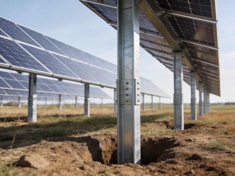
Soil conditions are the single largest driver of solar foundation cost variability across projects — more than wind speed, seismic zone, or project scale. The same 50 MWp solar installation on soft clay costs $0.028–$0.045/Wp for foundations; on medium-dense sand the same project costs $0.011–$0.019/Wp — a 2–4× cost range driven entirely by the geotechnical difference between the two sites. Understanding cost drivers by soil condition allows project developers to include realistic contingencies in financial models and allows geotechnical investigation to be treated as a cost-reduction tool rather than a project cost.
| Soil Condition | Foundation Cost Driver | Cost Relative to Medium Sand Baseline | Cost Reduction Strategy |
|---|---|---|---|
| Very Soft Clay (N < 5) | Long pile embedment + large concrete footing area + possible wick drain ground improvement | 2.5–4.0× baseline | Deeper investigation to find competent layer; consider pile clusters; evaluate ground improvement vs pile extension cost |
| Soft Clay (N 5–15) | Extended embedment depth; delayed set-up period before capacity testing | 1.5–2.5× baseline | CPT investigation to identify competent sub-layer; screw testing at multiple depths to optimize embedment; avoid over-conservative default depth |
| Medium-Dense Sand (N 15–35) | Standard embedment; baseline installation conditions | 1.0× (baseline) | Full CPT program to confirm uniformity; optimize post spacing to reduce foundation count |
| Gravel / Cobble (N > 40 with large fragments) | Pre-drilling for screw installation; rock-breaking tips for piles; specialist equipment | 1.8–3.0× baseline | Pre-construction test pile/screw to confirm drivability; evaluate rock anchor if bedrock is at ≤ 1.5 m depth |
| Shallow Rock (0–1.5 m) | Specialized drilling equipment; pre-production load testing; grout materials | 2.0–5.0× baseline (rock hardness-dependent) | Prioritize rock anchor design; avoid concrete with rock excavation (blasting cost prohibitive); soft rock reduces drilling cost significantly |
| High Groundwater (0–1 m depth) | Dewatering for concrete excavation; Class II–III corrosion specification; potential buoyancy uplift on concrete footings | 1.3–2.0× baseline (foundation type dependent) | Prefer pile or screw (no excavation dewatering required); specify corrosion class in procurement before bidding; design concrete footing with buoyancy check |
Geotechnical investigation conducted at the right scope — neither over-sampled (wasteful) nor under-sampled (structurally risky) — is the most economically leveraged investment in solar project pre-development. The complete cross-foundation-type cost analysis that quantifies foundation cost at different soil conditions and project scales is in the foundation cost comparison resource.
Geotechnical Engineering Design Checklist
- Soil investigation report validated by licensed geotechnical engineer: investigation scope confirmed as adequate for project size (minimum boring/CPT frequency per site variability classification); all SPT N-values corrected to N60 or N1,60 with documented energy correction factor CE; geotechnical engineer’s written recommendations for foundation type, bearing capacity, and pile/screw capacity parameters included in the report
- Bearing capacity calculated for governing load combination at design foundation level: qult calculated from Terzaghi or Hansen bearing capacity equations using laboratory-derived c’ and φ’; qa = qult/FS with FS ≥ 2.5–3.0 for solar foundations; eccentricity check performed (e ≤ B/6 for no-tension bearing condition under overturning moment from wind)
- Frost depth confirmed from local frost index data and cross-checked with borehole observations: Air Freezing Index (AFI) from NOAA or local climate records; frost penetration depth calculated per modified Berggren formula or local code table; soil frost susceptibility class determined from grain size and Atterberg limits; minimum foundation embedment confirmed ≥ frost depth + 200 mm
- Soil corrosion classification determined from field and laboratory chemistry: soil resistivity (Wenner 4-pin), pH, sulfate, and chloride measurements at foundation embedment depth; corrosion class assigned per ANSI/AWWA C105 or ISO 9223 for soil environments; metallic foundation element protection specification confirmed in procurement documents
- Seismic site class determined and liquefaction check completed where applicable: Vs30 estimated from N-value correlation or measured by MASW; Site Class per ASCE 7-22 §20.3; SDS and SD1 calculated with Fa and Fv amplification for the assigned Site Class; liquefaction potential evaluated per Youd et al. (2001) simplified procedure at all SPT boring locations in SDC C–F areas
- Uplift resistance calculation performed for governing wind load combination: factored net uplift Tu = 1.0Wnet uplift − 0.9Ddead per ASCE 7-22 LRFD Combination 7; pile tension skin friction or screw uplift capacity (Kt × T × 0.9) or concrete dead weight resistance confirmed ≥ Tu with documented safety factor
- Settlement analysis performed for concrete footings on compressible soil: immediate elastic settlement from elastic theory (B × q × (1−ν²)/Es × Is); primary consolidation settlement from oedometer test (Cc method); differential settlement between adjacent footings estimated from spatial variability of consolidation parameters; confirmed < 25 mm differential settlement limit for tracker systems
- Investigation adequacy confirmed relative to design sensitivity: confirm that the spacing and depth of borings or CPT soundings is sufficient to detect the geotechnical variability that would materially affect foundation design — thin weak layers at critical embedment depths, localized rock outcrops, and perched water table zones are the most commonly missed conditions in under-sampled investigations
Failure Risks & Common Geotechnical Mistakes
Ignoring Soil Report Data: Proceeding to Foundation Design Without Adequate Investigation
The most consequential geotechnical mistake in solar foundation engineering is proceeding to structural foundation design using assumed or regional default soil parameters rather than project-specific investigation data. Assumed parameters from regional soil maps or geological surveys are typically presented as ranges (e.g., “alluvial clay: qa = 75–200 kPa”) — using the upper bound to minimize foundation size while actual site conditions correspond to the lower bound produces foundations that are under-designed by a factor of 2.0–2.7 for bearing capacity. The failure mode is not immediate structural collapse (concrete footings overloaded in bearing typically exhibit visible settlement and tilting rather than sudden failure) but progressive differential settlement and lateral displacement over 2–5 years that misaligns the solar array, distorts racking connections, and eventually requires expensive remediation including screw jacking of footings, supplementary pile installation, or full foundation replacement.
Underestimating Settlement: Treating Settlement as a Secondary Check
Settlement is consistently under-estimated in solar foundation design because the governing structural calculation (bearing capacity) passes with apparent safety factor ≥ 2.5, creating a false sense of foundation adequacy while the serviceability limit state (settlement) governs unnoticed. Differential settlement between adjacent concrete footing positions of 25–50 mm is sufficient to misalign single-axis tracker drives, jam the rotation mechanism, and cause permanent yield in the racking connection hardware — none of which is detected by bearing capacity calculations alone. The engineering control: settlement analysis is not optional for concrete footings on any cohesive soil — it is a parallel design check that must be completed before foundation sizing is finalized, using site-specific oedometer test data for the consolidation parameters. Selecting pile foundations over concrete footings on compressible clay specifically because piles extend to a competent non-compressible layer below the clay avoids the settlement problem entirely — a structural argument for pile selection independent of bearing capacity.
Incorrect Bearing Capacity Assumption: Using Surface Values at Depth or Vice Versa
A systematic error in solar foundation bearing capacity calculations is applying the geotechnical engineer’s recommended allowable bearing capacity at the wrong depth. Bearing capacity is depth-dependent — qa increases with foundation embedment depth due to increasing overburden stress (Nq term in the bearing capacity equation); qa at 1.5 m embedment is typically 30–60% higher than qa at 0.5 m embedment in the same soil. The geotechnical report typically provides qa at the proposed foundation bearing level — using a shallower-depth qa value for a deeper foundation over-designs the footing (conservative but costly); using a deeper-depth qa for a shallower foundation under-designs it (unconservative and potentially structurally inadequate). The structural engineer must confirm the exact depth at which the reported qa applies before using it in footing design calculations.
Inadequate Frost Consideration: Embedment Governed by Capacity, Not Frost Depth
Specifying foundation embedment depth based solely on the structural capacity calculation — stopping at the depth where pile skin friction, screw torque, or concrete dead weight meets the structural requirement — without confirming that this depth also places the bearing element below the local frost penetration depth is a code violation (IBC 2024 §1809.5) and a structural failure risk. The failure mode is frost heave: seasonally frozen frost-susceptible soil above the helix plate or pile tip develops upward jacking force that displaces the foundation element upward by 20–80 mm over a winter-spring cycle, tilting the solar mounting column and eventually fracturing the column-to-racking connection. Frost heave damage is most commonly observed at foundations installed at “adequate capacity depth” that is shallower than frost depth — the capacity criterion was met but the frost criterion was not checked. Both criteria must be satisfied simultaneously; the minimum embedment depth is the greater of the structurally required depth and the frost-required depth.
Frequently Asked Questions
What soil investigation is required before selecting a solar foundation type?
The minimum geotechnical investigation required before foundation type selection for a solar project depends on project scale: for projects < 1 MWp, a minimum of 3 SPT borings to 3 m depth with soil classification and groundwater observation is adequate for standard soil conditions; for 1–10 MWp, minimum 5–10 borings at representative locations (one per 5 acres) or CPT soundings at one per 3 acres, with at least 2 laboratory test suites (grain size, Atterberg limits, direct shear or triaxial, consolidation if clay is present); for > 10 MWp, a systematic investigation program with boring or CPT spacing ≤ 3 acres in uniform soil or ≤ 2 acres in variable soil, seismic site class determination (Vs30 measurement in SDC B and higher), and full laboratory program including consolidation testing if compressible clay is present at any foundation depth. Projects that skip geotechnical investigation to save $20,000–$50,000 in pre-development cost routinely spend $200,000–$1,000,000 in foundation redesign, change orders, and construction delays when undiscovered adverse soil conditions are encountered during installation.
How does soil type affect the choice between ground screws and driven piles?
Soil type is the primary technical factor governing the ground screw vs driven pile decision after commercial and schedule considerations are set aside. Ground screws are structurally superior to driven piles in: medium-stiff clay (N 10–25, su 50–100 kPa) where screw helix bearing provides reliable capacity with torque verification; medium-dense sand (N 15–35) where torque correlation is most reliable and installation rate is fastest; sites with vibration restrictions or noise ordinances prohibiting impact driving. Driven piles are structurally superior to ground screws in: very dense sand and gravel (N > 35, φ’ > 36°) where impact energy advances the pile past cobbles and dense layers that stop screws; soft clay (N < 10) where pile set-up effect over time produces higher long-term capacity than the initial torque-correlated screw capacity; large-scale (>50 MWp) projects where large hammer rig installation rates (500+ per day) are not achievable with screw rigs; and high-lateral-stiffness demand applications where H-pile or pipe pile sections provide significantly higher EI than equivalent tube screw sections.
xml
What does bearing capacity mean for solar foundation design? (continued)
(2) Allowable bearing capacity qa: qult divided by a factor of safety (FS = 2.5–3.0 for solar foundations per IBC 2024 §1806.3); this is the design pressure limit used in footing sizing calculations; qa = qult/FS. For concrete footings, the structural check is: qapplied = Pcolumn/Afooting ≤ qa — the applied contact pressure must not exceed the allowable bearing capacity. For pile and screw foundations, bearing capacity governs the end bearing capacity component at the pile tip or helix plate: Qb = Atip × qb where qb is the unit end bearing pressure at the pile tip depth. Bearing capacity is a site-specific parameter — it cannot be assumed from regional soil maps or geological descriptions; it must be calculated from site-specific shear strength parameters (su from UU triaxial or unconfined compression for clay; φ’ from direct shear or CU triaxial for sand) at the governing foundation bearing depth.
How does groundwater depth affect solar foundation design?
Groundwater table depth affects solar foundation design through four independent mechanisms: (1) Effective stress reduction: soil below the groundwater table has effective unit weight γ’ = γsat − γw ≈ 8–11 kN/m³ instead of γbulk ≈ 17–20 kN/m³; bearing capacity and pile skin friction in sand decrease proportionally with effective stress below the water table — for piles in sand, skin friction in the saturated zone is approximately 40–55% of the value in equivalent soil above the water table at equivalent depth; (2) Concrete footing buoyancy: concrete below the water table experiences upward buoyancy force = γw × Vsubmerged; for a 0.8 m × 0.8 m × 1.0 m deep concrete footing fully submerged: Fbuoyancy = 9.81 × (0.64 m²) × 1.0 m = 6.3 kN — reducing the effective dead weight resisting wind uplift; if uplift resistance is governed by concrete dead weight, the buoyancy force directly reduces the available uplift resistance and must be included in the uplift check; (3) Corrosion class escalation: metallic foundations partially submerged in groundwater experience the most aggressive corrosion condition — the tidal zone effect at the water table elevation, where alternating wet-dry cycling with full oxygen availability produces corrosion rates 2–5× higher than either permanently submerged or permanently dry conditions; Class II minimum (double protection) is mandatory for metallic foundations crossing the groundwater table; (4) Concrete excavation dewatering: groundwater within 0.5 m of the excavation base requires active dewatering by well points or sump pumping before concrete placement — adding $500–$2,000 per footing in labor and equipment, making ground screw or pile foundations (requiring no excavation) significantly more cost-competitive than concrete when shallow groundwater is present across the project footprint.
What is the difference between SPT and CPT investigation, and which should I use?
SPT (Standard Penetration Test) and CPT (Cone Penetration Test) provide complementary soil profile information through fundamentally different measurement mechanisms. SPT drives a sampler to measure blow count resistance at discrete 1.5 m depth intervals and retrieves a physical soil sample for classification and laboratory testing — the discontinuous N-value profile is the primary limitation, as critical weak layers thinner than 1.5 m may fall between test intervals and go undetected. CPT pushes an instrumented cone at constant rate (20 mm/s) and records tip resistance qc, sleeve friction fs, and pore pressure u2 at continuous 20 mm depth increments — the 75× finer resolution profile reliably identifies thin weak layers, sand lenses in clay, and gradational transitions between soil types. Selection guidance: use SPT borings as the primary investigation method at sites where physical soil samples are needed for laboratory testing (consolidation, Atterberg limits, grain size) or where rock is expected (SPT can core into rock); use CPT as the primary profiling method at large flat sites with variable alluvial soils where continuous layer detection is more important than physical samples; use CPT + 2 SPT borings per formation zone to get both continuous profiles and physical samples. For pure cost efficiency at sites > 5 MWp with uniform soil, CPT at close spacing + sparse SPT borings for laboratory specimens provides the best investigation value.
How does soil variability across a large solar site affect foundation design?
Soil variability across a large utility-scale solar site — the normal condition at most project locations, which occupy 200–2,000 acres of land that spans multiple depositional environments, fills, and erosional features — requires that foundation design accommodate a range of soil conditions rather than a single design profile. Three design approaches for variable-soil large solar sites: (1) Zone-based design: divide the project footprint into geotechnical zones based on investigation data; provide a different foundation specification (pile length, screw embedment depth, footing dimension) for each zone; most cost-efficient approach but requires adequate investigation density to define zone boundaries accurately; (2) Conservative single design: design all foundations for the worst soil zone identified in investigation; over-designs foundations in better soil zones but simplifies procurement and construction; appropriate when soil variability is moderate and the cost penalty for conservative design is smaller than the management cost of zone-based specification; (3) Torque-based field adjustment (ground screws only): install ground screws to the minimum structural depth; continue installation until the design torque threshold is achieved; record actual installation depth for each screw; screws in weak soil zones automatically go deeper to achieve torque; screws in strong soil zones achieve torque at lesser depth — a self-adjusting system that optimizes screw length to the actual soil encountered without requiring pre-determined zone boundaries. Approach (3) is the commercially optimal strategy for large variable-soil sites using ground screws, eliminating the cost of over-designed zones while maintaining structural adequacy in weak zones.
What geotechnical conditions make solar foundation installation most challenging?
Five geotechnical conditions rank as the most structurally and commercially challenging for solar foundation installation: (1) Soft clay with su < 20 kPa in the full embedment zone: very long pile or screw embedment required; installation equipment sinks in the soft surface clay; driven pile set-up period delays load testing; concrete footing requires enormous plan area; (2) SPT refusal cobbles in the upper 1–2 m overlying soft soil: the surface cobble layer defeats screw and pile installation but the underlying soil is too soft for standard shallow foundations — requires pre-drilling through the cobble layer with specialized equipment before screw or pile installation; (3) Liquefiable loose sand at SDC D–F: all foundations must extend well below the liquefiable zone — adding 2–5 m to required pile or screw embedment; ground improvement (vibrocompaction or stone columns) may be required if liquefiable layer is too thick to bypass economically; (4) Highly variable rock depth (0–5 m depth variation within a single array block): requires CPT or probe drilling at every foundation position before specifying foundation type — some positions need rock anchors, others need soil-based foundations at the same array block; mixed foundation types within one block complicate racking design and column height standardization; (5) Expansive clay (PI > 30, high montmorillonite content): seasonal shrink-swell volume changes in expansive clay impose cyclic vertical displacement on shallow foundations of 15–60 mm annually in dry/wet seasonal climates — potentially exceeding tracker drive tolerances if foundation design does not extend below the active zone depth where seasonal moisture change is negligible.
How does geotechnical investigation reduce the total project cost of solar foundations?
Geotechnical investigation reduces total solar foundation project cost through five documented mechanisms: (1) Right-sizing foundation design: site-specific qa and su data eliminates the need to design for worst-case assumed conditions — a project designed on actual soil data versus conservative default assumptions typically achieves 15–35% reduction in concrete volume, pile length, or screw embedment depth; (2) Foundation type optimization: investigation that reveals a competent sand layer at 1.2 m depth beneath 0.5 m of soft clay allows selection of ground screws designed to reach the competent layer — at 40% lower cost than concrete footings sized for the soft clay bearing capacity; (3) Eliminating construction change orders: the most expensive category of geotechnical cost — discovered-during-construction soil problems (refusal at shallow depth, soft clay encountered below assumed bearing level, groundwater at excavation base) — are entirely preventable by adequate pre-construction investigation; change order costs typically range from $50,000–$500,000 on projects where geotechnical investigation was inadequate; (4) Enabling performance-based procurement: site-specific investigation data allows the foundation contractor to bid based on confirmed soil conditions rather than adding risk contingency for uncertain conditions — typical risk contingency in foundation contractor bids for sites without adequate investigation: 15–25% of base bid; (5) Confirming installer performance: the geotechnical report’s pile capacity and screw torque parameters provide the acceptance criteria for production installation testing — without this data, the structural engineer cannot certify that the installed foundations meet the structural requirements, potentially blocking lender technical due diligence sign-off. Complete solar load transfer design calculations that quantify the cost-performance relationship between soil quality and foundation structural efficiency across all foundation types are in the load transfer principles resource.
Related Engineering Topics
The geotechnical parameters characterized in soil and geotechnical investigation directly feed into several parallel engineering design streams that together constitute the complete solar foundation and structural design package. Each topic below requires geotechnical input as a prerequisite:
- Wind load calculation — Wind pressure on solar arrays determines the design uplift and lateral forces that foundation capacity must resist; wind load calculation per ASCE 7-22 Chapters 26–29 requires the site exposure category (determined in part from surface roughness classifications that depend on the surrounding terrain — a geotechnically characterized site description contributes to the exposure category determination); wind load is the demand side of the foundation capacity equation that the geotechnical supply side (bearing capacity, pile skin friction, screw torque) must satisfy with the required safety factor
- Seismic design — Seismic design spectral accelerations SDS and SD1 — the primary inputs to the equivalent lateral force procedure (ASCE 7-22 §12.8) — are directly amplified by the geotechnical site class (Fa and Fv factors from ASCE 7-22 Tables 11.4-1 and 11.4-2); Site Class E (soft clay, Vs30 < 180 m/s) produces amplification factors up to Fa = 2.5–3.5 at low spectral accelerations — more than doubling the seismic design force relative to a rock site at the same mapped SS; seismic design cannot be completed without first characterizing the geotechnical site class from the investigation data
- Frost depth design — Frost penetration depth — derived from the Air Freezing Index for the project location combined with the soil frost susceptibility class from grain size and Atterberg limits in the geotechnical report — sets the minimum foundation embedment depth that overrides structural capacity calculations in cold-climate solar projects; frost heave force calculations for adfreeze on pile and screw shafts require the geotechnical report’s frost susceptibility classification and unit weight data to quantify the jacking force that cold-climate foundations must be designed to resist at the column base connection
- Foundation corrosion protection — Soil corrosion aggressiveness classification — from soil resistivity, pH, sulfate, and chloride measurements in the geotechnical investigation — is the governing input for metallic foundation protection class specification; without site-specific soil chemistry data from the geotechnical investigation, corrosion class specification defaults to the most conservative (most expensive) Class III, adding 25–60% to material cost for ground screws and piles; site-specific investigation that confirms low-aggressiveness soil chemistry (ρ > 5,000 Ω·cm, pH 6–8, SO₄ < 500 mg/kg) allows specification of Class I protection, reducing material cost to the minimum technically justified level
- Load transfer principles — The structural mechanics of load transfer from solar mounting columns into soil — pile skin friction distribution, screw helix bearing, concrete footing pressure distribution, rock anchor bond stress — requires soil property inputs (su, φ’, qa, kh) from the geotechnical investigation; load transfer calculations cannot be performed to a professional standard without site-specific geotechnical parameters; the load transfer resource provides the structural calculation framework that consumes the geotechnical investigation outputs to produce verified foundation capacity values for permit and lender documentation
Prepare for project-specific review
Use this guide to organize the site, load, system and compliance inputs that a product supplier, licensed engineer, installer or local authority will need. PVRack does not provide project-specific engineering approval or supplier quotations.