
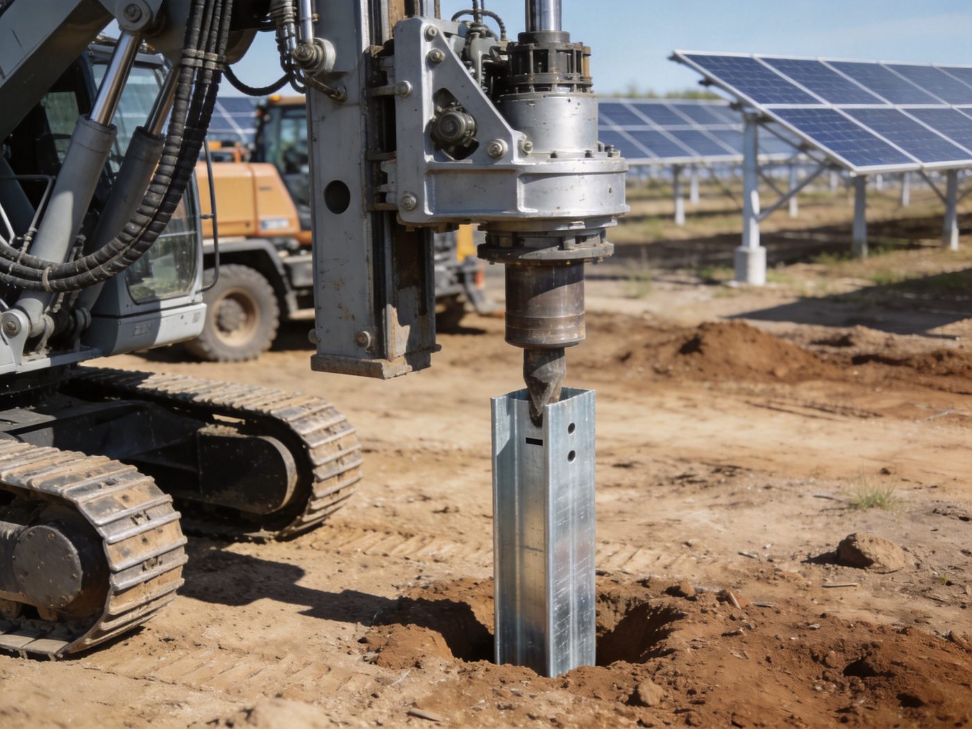
Pile driven foundations are the dominant foundation solution for utility-scale solar mounting worldwide — accounting for the majority of ground-mounted solar installations globally because they deliver the optimal combination of installation speed, soil adaptability, structural reliability, and long-term load capacity without concrete or excavation. A pile driven foundation transfers all solar mounting structural loads — wind uplift, wind lateral force, gravity, and seismic — directly into the soil through a steel section driven to design embedment depth, relying on the soil-steel interface to develop skin friction resistance and end-bearing resistance that together provide the axial, lateral, and uplift capacity required by the solar mounting structural system above. Pile driven systems are one of the most widely used solar foundation systems for large-scale projects — and for a complete overview of all foundation types, comparative selection criteria, and site-specific application guidance, see our Solar Foundation Systems Guide, the authoritative engineering reference for solar foundation design across all terrain, soil, and climate conditions.
The engineering decision to specify pile driven foundations over concrete, ground screw, or ballasted alternatives is driven by three quantifiable parameters: installation speed (piles driven at 200–400 per day per rig versus concrete poured at 40–80 foundations per day per crew); soil range (pile driving viable in cohesive clay, loose sand, gravel, and weak rock to refusal, where ground screws lose torque correlation and ballasted systems are structurally inadequate); and structural performance under combined wind uplift and lateral loading, where driven steel sections develop the highest lateral stiffness per unit embedment depth of all non-concrete foundation types.
Technical Snapshot: Pile Driven Foundation Performance Parameters for Solar Mounting
| Parameter | Typical Range / Value | Governing Condition | Engineering Note |
|---|---|---|---|
| Embedment Depth | 1.2–2.5 m typical; 2.5–4.0 m in soft cohesive soil or high-uplift environments; 0.8–1.2 m in dense gravel to refusal | Soil bearing capacity, frost depth, uplift demand, lateral stiffness requirement | Embedment depth governs pile material cost per unit more than any other parameter; deep embedment in soft soil may require section upgrade from W-section to H-pile or pipe pile to maintain drivability without section damage |
| Section Type | C-channel (75×40–100×50 mm); W-section (W6×9–W8×31); H-pile (HP8×36–HP10×42); square tube (60×60–100×100 mm, t = 4–6 mm); round pipe pile (89–114 mm OD, t = 4–6 mm) | Lateral load demand, soil type, driving resistance, section availability | C-channel and W-sections are standard for most utility-scale solar at normal soil; H-pile and pipe pile required at hard driving conditions or very high lateral demand; square tube popular for tracker systems where drive arm attachment height is precise |
| Axial Compression Capacity | 80–350 kN per pile depending on section, embedment, and soil | Dead load + snow load at maximum tributary area | Axial compression rarely governs solar mounting pile design — wind uplift and lateral load typically govern; verify axial capacity at tracker drive column positions where panel dead load is highest |
| Uplift Capacity | 25–180 kN per pile depending on section perimeter, embedment depth, and soil adhesion | Wind uplift at array edge piles under ASCE 7-22 LRFD Combination 7 (0.9D + 1.0W) | Uplift capacity = skin friction along embedded pile perimeter; scales with section perimeter × embedment depth × unit skin friction (α × su for cohesive soil; K × σ’v × tan(δ) for cohesionless soil); uplift governs foundation design at array corners and perimeter rows in high-wind coastal sites |
| Lateral Load Capacity | 5–45 kN per pile at 10 mm head displacement; governed by pile stiffness (EI) and soil lateral reaction modulus (kh) | Wind lateral force on column; seismic base shear; tracker drive arm lateral reaction | Lateral capacity is stiffness-governed (pile head deflection limit, typically 10–15 mm) rather than strength-governed for standard solar mounting sections; increasing section moment of inertia I (deeper section or heavier wall) more effectively improves lateral stiffness than increasing embedment depth beyond 2× the characteristic length T = (EI/kh)^0.25 |
| Installation Speed | 200–500 piles/day per hydraulic impact hammer rig; 150–300 piles/day per vibratory driver | Soil type (dense gravel and cobble reduce rate); pile section (larger sections reduce rate); access (row spacing determines rig repositioning time) | Pile driving is the fastest solar foundation installation method for ≥50 piles/day projects; vibratory driving preferred in urban or noise-sensitive sites; impact hammer required in dense soils and for high-capacity pile verification testing |
| Corrosion Design Life | 25–40 years with standard HDG 85 µm coating; 40–60 years with duplex coating (HDG + epoxy topcoat) in C3–C4 soil; ≥50 years with sacrificial anode cathodic protection in C4–C5 soil | Soil ISO corrosion category (C2 dry inland to C5 coastal/industrial); groundwater presence; soil pH and chloride content | Below-grade corrosion rate in soil is 3–5× higher than above-grade atmospheric corrosion at equivalent ISO category; pile section loss is irreversible — specify corrosion protection system for below-grade embedded length that achieves design life at the site-specific soil corrosion category |
What Is a Pile Driven Foundation for Solar Mounting?
Core Structural Concept
A pile driven foundation is a structural element — typically a steel section — that is installed into the soil by dynamic impact or vibratory force to a design embedment depth, without pre-excavation or post-placement concrete. The fundamental structural mechanism is direct soil-steel load transfer: the embedded section develops resistance to applied loads through (1) skin friction between the steel surface and the surrounding soil along the full embedded length, and (2) end bearing at the pile tip where the section bears against a stiffer soil layer or rock. Unlike concrete spread footings or pad foundations that transfer load through a horizontal bearing area at the base of a shallow excavation, pile driven foundations transfer load through a vertical surface area — the pile perimeter × embedment depth — making them uniquely efficient in soft or compressible soils where shallow bearing capacity is insufficient and in constrained right-of-way environments where excavation is impractical. The structural engineering principles that govern how loads applied at the pile head (from the solar mounting column above) are distributed through the soil-pile interface and into the surrounding soil are formalized in the framework of load transfer principles — the foundational engineering reference that underpins all pile foundation capacity calculations for solar mounting systems.
Key Components of a Pile Driven Foundation Assembly
A complete pile driven foundation assembly for solar mounting comprises five structural components, each with a defined engineering function: (1) Pile section: the primary structural element driven into soil; cross-section geometry (C-channel, W-section, H-pile, tube, pipe) determines lateral stiffness EI, skin friction perimeter, and drivability characteristics; (2) Pile tip: the bottom end of the section, which may be open (standard for pipe piles) or closed with a welded plate or conical tip to prevent soil ingress and improve end bearing in gravel or rock; (3) Pile cap / head plate: a factory-welded plate or machined coupler at the top of the pile section that receives the solar mounting column base plate connection; tolerances at the pile head (±15–25 mm horizontal, ±10 mm vertical) determine whether the racking base plate can be attached without shim plates; (4) Corrosion protection layer: hot-dip galvanizing, fusion-bonded epoxy, or duplex coating applied to the full pile section (both above and below grade) before driving; coating integrity in the below-grade zone is critical because post-installation coating repair of embedded pile surfaces is impossible; (5) Driving indicator system: paint marks at 250 mm intervals along the pile section that serve as depth indicators during driving and as proof of embedment at QA inspection after installation. The site investigation data that governs pile section selection, embedment depth specification, and corrosion category determination comes from the soil and geotechnical considerations analysis — without site-specific soil investigation, pile design embedment depths and section specifications cannot be structurally validated.
When Engineers Choose Pile Driven Foundations
Structural engineers and EPC project managers specify pile driven foundations when the following site and project conditions align: (1) Scale ≥ 1 MWp: below 1 MWp, mobilization cost of pile driving equipment relative to total foundation cost favors ground screws or manual installation methods; at ≥ 5 MWp, pile driving achieves the lowest cost per foundation of all non-ballasted systems in most soil conditions; (2) Soil: medium-dense to soft cohesive or cohesionless: pile driving performs best in soils with SPT N-value 5–40 (very soft clay to medium-dense sand); N < 5 (very soft clay) requires embedment depth verification for lateral capacity; N > 50 (dense gravel, cobble, or rock) limits driving to refusal at shallow depth and may require pre-drilling or alternative foundation type; (3) Flat to gently sloping terrain (0–15% grade): pile driving rigs require relatively flat working surface; steep terrain (>15% grade) requires specialized rigs or prohibits standard pile driving; (4) No concrete requirement: projects with tight schedules or remote sites where concrete supply is logistically constrained benefit from the concrete-free pile installation workflow; (5) High wind or seismic demand: driven steel piles provide the highest lateral stiffness per unit cost of all non-concrete foundation types in standard soils, making them the preferred structural choice when wind lateral force or seismic base shear demand is high.
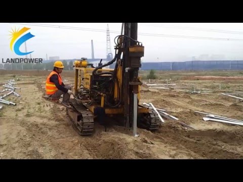
Video: ground screw / pile driving for PV projects.
Engineering Principles Behind Pile Driven Foundations
Axial Load Resistance: Skin Friction and End Bearing
The axial compressive capacity of a driven pile is the sum of skin friction resistance along the embedded pile perimeter and end bearing resistance at the pile tip. For steel piles in cohesive soil (clay), skin friction resistance per unit depth is: fs = α × su, where α = adhesion factor (0.5–1.0 depending on pile surface roughness and soil overconsolidation ratio; typically 0.6–0.8 for standard HDG steel sections in normally consolidated clay); su = undrained shear strength (kPa) from laboratory testing or CPT correlation. Total skin friction capacity: Qs = Σ(fs,i × As,i) where As,i = perimeter × depth increment for each soil layer. End bearing capacity at pile tip in clay: Qb = 9 × su,tip × Atip. For solar mounting piles where axial compression from dead load is typically 5–15 kN per pile (panel weight + mounting hardware weight), skin friction alone at 1.5–2.0 m embedment depth in medium clay (su = 40 kPa) provides Qs ≈ 0.7 × 40 × (0.30 m perimeter) × 1.8 m = 15.1 kN — which satisfies the compression demand with safety factor FS > 2.0 at standard embedment. The governing axial limit state for solar piles is typically uplift under wind loading, not compression.
Lateral Load Performance: Stiffness and the Characteristic Length
Lateral load capacity of a driven pile is governed by the pile’s flexural stiffness EI and the soil’s lateral reaction modulus kh (kN/m³) — the subgrade reaction that resists pile lateral displacement per unit depth. The characteristic length T = (EI/kh)^0.25 (metres) defines the depth over which the pile-soil system effectively develops lateral resistance — piles longer than approximately 4T behave as “long” piles where additional embedment depth beyond 4T provides negligible additional lateral capacity. For a standard W6×9 steel section (E = 205,000 MPa; I = 16.0 cm⁴) in medium-dense sand (kh = 15,000 kN/m³): T = (205,000 × 16.0 × 10⁻⁴/15,000)^0.25 = (0.219)^0.25 = 0.685 m; 4T = 2.74 m. Driving this section to 2.0 m embedment achieves approximately 85% of the lateral capacity of infinite embedment — driving to 3.0 m (beyond 4T = 2.74 m) provides less than 3% additional lateral capacity. This T-value analysis explains why increasing embedment depth beyond 4T for lateral load improvement is structurally ineffective — the correct engineering response to insufficient lateral capacity is to increase the pile section moment of inertia I (use a deeper or heavier section) rather than drive deeper. Detailed solar load transfer design across the complete soil-pile-structure interaction is developed in the solar load transfer design resource.
Uplift Resistance Mechanism
Uplift resistance — resistance to the upward tensile force produced by wind uplift acting on the solar panel array — is the governing design limit state for solar mounting pile foundations at high-wind sites. The uplift mechanism in driven piles is exclusively skin friction: there is no “hook” or “bell” at the pile tip as in belled caissons; the entire uplift resistance comes from the shear stress mobilized at the steel-soil interface along the embedded length as the pile is pulled upward. Uplift skin friction is typically 70–80% of compressive skin friction for driven piles, because soil relaxation adjacent to the pile during upward displacement slightly reduces the normal stress on the pile surface. For the ASCE 7-22 governing uplift load combination (0.9D + 1.0W at array edge), net uplift force at a corner pile in a high-wind coastal installation can reach 30–60 kN — requiring 1.8–2.5 m embedment in medium clay (su = 40 kPa) for a standard C-channel section with 0.30 m perimeter. At sites with low undrained shear strength (very soft clay, su ≤ 20 kPa), achieving the required uplift capacity may require a section with larger perimeter (H-pile or pipe pile) or embedment depths exceeding 3.0 m — both of which have significant cost implications that must be identified during site investigation rather than discovered during construction.
Soil Friction and End Bearing in Cohesionless Soils
In cohesionless soils (sand, gravel), skin friction resistance is computed by the effective stress method: fs = K × σ’v × tan(δ), where K = lateral earth pressure coefficient acting on the pile surface (0.5–1.0 for driven piles in loose to medium-dense sand; higher K for displacement piles with larger cross-sections that compact the surrounding soil during driving); σ’v = effective vertical stress at depth z = γ’× z; δ = interface friction angle between steel surface and soil (typically 0.67–0.75 × φ’ for smooth steel; higher for rough or galvanized surfaces). In dense gravel and cobble, end bearing at the pile tip contributes significantly to total axial capacity: Qb = Nq × σ’v,tip × Atip, where Nq = bearing capacity factor (30–50 for dense sand; higher for gravel). For driven piles in cohesionless soils, the key design consideration is the critical depth effect: σ’v does not increase linearly with depth in very long piles because arching effects in the soil limit the effective vertical stress increase beyond a critical depth of approximately 10–20 pile diameters. This effect means that doubling pile embedment depth does not double uplift capacity in cohesionless soils at depths beyond the critical depth — a nuance that must be addressed in pile capacity calculations for deep embedment applications.
Structural Anatomy & Cross-Section Breakdown
Embedment Depth Design: Balancing Uplift, Lateral, and Frost Requirements
Pile embedment depth for solar mounting foundations is governed by the most demanding of three independent requirements: (1) Uplift capacity: embedment depth Duplift is the minimum depth at which skin friction resistance Qs,uplift ≥ factored net uplift demand Tu with factor of safety FS = 2.0 (ASD) or resistance factor φ = 0.35–0.45 (LRFD); in soft clay (su = 25 kPa), a C-channel with perimeter 0.28 m requires Duplift = Tu/(0.7 × α × su × perimeter) = 40/(0.7 × 0.7 × 25 × 0.28) = 11.6 m — an extreme requirement indicating that very soft clay requires a different foundation type (helical pile, concrete pad, or ground anchor) rather than a driven pile with unrealistic embedment; (2) Lateral capacity: embedment depth Dlateral must provide the pile head deflection ≤ 10–15 mm under design lateral force; for most solar mounting sections and soil conditions, Dlateral = 4T (as discussed above) governs in soft to medium soils; in dense sand or gravel, Dlateral may be only 1.0–1.5 m because kh is high; (3) Frost depth: in cold climates, the pile must extend below the local frost penetration depth to prevent frost heave — seasonal freezing of soil adjacent to the embedded pile creates an upward frost-jacking force that can gradually displace a pile with insufficient embedment below the frost line. Frost depth governs in Canadian, Scandinavian, and northern US projects where frost penetration reaches 0.8–2.4 m and may be the controlling embedment requirement in high-bearing-capacity soils where structural capacity is achieved at shallower depths.
Steel Section Profiles: Selection Criteria by Application
Five steel section types are used for driven solar mounting piles, each optimized for specific combinations of structural demand, soil condition, and installation method. C-channel (cold-formed or hot-rolled, 75×40–150×65 mm): the standard section for utility-scale ground-mount solar at normal soil conditions (SPT N = 10–35); low material cost per metre; adequate lateral stiffness for post heights ≤ 1.5 m; open section limits drivability in dense or cobbly soils where section damage at the tip becomes a concern. W-section (W6×9 to W8×31): higher moment of inertia than C-channel for equivalent mass; preferred for high-wind sites requiring greater lateral stiffness; the wide flange also provides higher skin friction perimeter for equivalent section mass — improving uplift capacity per kilogram of steel; drivability comparable to C-channel in standard soils. H-pile (HP8×36 to HP12×53): heavy displacement section for hard driving conditions (SPT N > 40, dense gravel, weak rock); the equal-flange equal-web geometry resists driving damage at the pile tip better than asymmetric sections; significantly higher material cost than C-channel or W-section, justified only where standard sections cannot be driven to required embedment without section damage. Square hollow section (SHS, 60×60–100×100 mm, t = 4–6 mm): preferred for single-axis tracker installations where the post-to-drive-arm connection geometry requires a square section for torque arm attachment; uniform moment of inertia in both plan axes (Ix = Iy) is structurally optimal for tracker systems where lateral wind force direction varies throughout the day. Circular pipe pile (89–114 mm OD, t = 4–6 mm): highest lateral stiffness per unit mass for equivalent section depth due to the closed circular section geometry; preferred in coastal high-wind applications requiring maximum lateral capacity; higher material cost than open sections; tip should be closed-end for driving in loose cohesionless soils to prevent soil plug blow-out.
Corrosion Protection Layer: Below-Grade and Above-Grade Requirements
The corrosion protection specification for a driven pile must address two structurally independent zones: the above-grade zone (above soil surface, typically 0.5–2.5 m exposed to atmospheric corrosion) and the below-grade zone (embedded section exposed to soil and groundwater corrosion). Above-grade protection follows atmospheric ISO 12944 categories — standard HDG 85 µm per EN ISO 1461 is adequate for C1–C3 above-grade; duplex coating (HDG + polyester topcoat) for C4–C5 above-grade at coastal sites. Below-grade protection requires soil corrosion category assessment: soil pH, chloride content, resistivity, and moisture content determine the soil corrosion aggressiveness. Below-grade corrosion rates for uncoated steel in typical soils range from 10–25 µm/year in C2 dry inland soil to 50–100 µm/year in C4–C5 coastal saturated soil — a section thickness loss of 1.25–2.5 mm over 25 years in aggressive soil that could reduce a 4.0 mm wall pile section to 1.5–2.75 mm effective thickness, potentially below structural minimum. The complete below-grade corrosion protection specification — including cathodic protection options (sacrificial anode, impressed current) for aggressive soil environments — is developed in the foundation corrosion protection resource.
Bracket and Racking Interface: Pile Head Tolerance and Connection Design
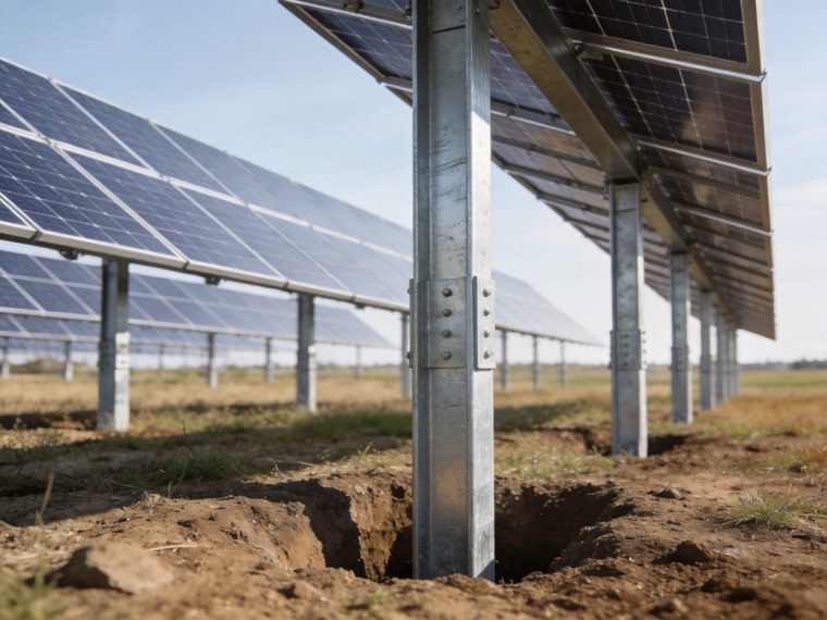
The pile head interface — where the driven pile meets the solar mounting column base plate — is the structural connection that transfers all solar mounting loads from the racking system to the foundation. Pile head connection design must accommodate two engineering realities: (1) Pile head position tolerance: pile driving achieves ±15–25 mm horizontal position tolerance and ±10–20 mm vertical elevation tolerance at the pile head; the base plate connection system must accommodate this tolerance range without structural compromise — typically through slotted holes in the base plate, adjustable height couplers, or slide-in column fittings that accept the positional variance; (2) Moment and shear transfer: at cantilever column piles (where the pile extends above grade and the racking column is the pile itself), the pile head carries the full overturning moment from wind loading with no connection required; at separate pile + column configurations, the base plate bolted connection must transfer the design shear and moment per the structural connection design requirements. Pile head elevation setting accuracy — achieved through electronic level survey at 100% of piles after driving — is a quality assurance requirement that directly affects solar mounting structural alignment, panel tilt angle accuracy, and tracker drive mechanism clearance.
Installation Workflow
Phase 1 — Pre-Construction Engineering Review
Pre-construction engineering review for pile driven foundation installation comprises five deliverables that must be completed before the first pile is driven: (1) Geotechnical investigation report: minimum one soil boring or CPT sounding per 2 acres of project area (one per 5 acres in uniform soil conditions); report must include SPT N-values or CPT qc values by depth, soil classification per USCS, groundwater table depth, and laboratory undrained shear strength (su) for cohesive soil layers; (2) Pile design drawings: stamped by Professional Engineer; must specify pile section, minimum embedment depth by zone (perimeter rows, interior rows, corner positions), corrosion protection specification, and pile head elevation tolerance; (3) Driving criteria: either a blow count per 25 mm penetration at target depth (for impact hammer driving) or a vibration frequency and set per cycle (for vibratory driving) that confirms adequate soil resistance at design embedment — derived from wave equation analysis (WEAP analysis) using the site soil profile and proposed driving equipment; (4) Pile load test program: for projects > 5 MWp or where soil conditions are highly variable, a static uplift load test to 2× design uplift load on minimum 1% of production piles (or minimum 3 test piles) confirms that the soil-pile system achieves design capacity; (5) Driving equipment submittal: contractor must submit proposed driving equipment (hammer type, ram weight, drop height or rated energy; or vibratory driver model and eccentric moment) for engineer review before mobilization. The foundation selection guide provides the complete decision framework for determining whether pile driven foundations are the appropriate selection for a given project, and what pre-construction engineering deliverables are required for each foundation type.
Phase 2 — Pile Driving Operations
Standard pile driving operations sequence for utility-scale solar installation: (1) Survey staking: pile positions surveyed from design layout file and staked at ±25 mm horizontal tolerance; stakes marked with pile ID and design embedment depth; (2) Rig positioning: hydraulic impact hammer rig (most common) or vibratory driver positioned over pile location; rig guides set to design pile orientation (vertical ± 1° for standard installations); (3) Pile insertion: pile section inserted into hammer guide; driving begins with reduced energy to establish direction; full driving energy applied after first 300 mm penetration; (4) Embedment monitoring: depth indicator paint marks on pile section counted during driving; driving terminated when (a) design embedment depth reached and driving resistance ≥ minimum blow count, OR (b) driving resistance reaches refusal (≤ 25 mm penetration in last 10 blows at full energy) before reaching design depth — refusal at shallow depth requires engineering review and may indicate unexpected cobble or rock layer requiring pre-drilling; (5) Pile head trimming: piles driven to excessive depth or insufficient depth within tolerance may require either acceptance with engineering re-verification or extraction and replacement — pile acceptance tolerance is typically ±50 mm from design embedment depth.
Phase 3 — Post-Installation Inspection and QA
Post-installation quality assurance for pile driven foundations requires three independent verification activities: (1) 100% pile head survey: electronic level survey of all installed pile heads within 24 hours of driving, recording actual x-y position and elevation against design; position deviation report generated for all piles outside ±25 mm horizontal and ±10 mm elevation tolerance; out-of-tolerance piles flagged for engineering disposition (accept with shim, re-drive, or replace); (2) Driving record review: driving logs (blow count per 25 mm or vibration frequency log per 100 mm) reviewed by structural engineer for all production piles; piles with anomalous driving records (sudden stop at shallow depth, no refusal, or irregular blow count progression) require investigation — these may indicate pile damage during driving, obstructions in the pile path, or inadequate soil contact; (3) 5% random torque verification (for piles with top-connection hardware): confirm that pile head bracket bolts achieve specified installation torque at randomly selected 5% sample within 48 hours of installation.
Performance Analysis
Wind Resistance Capacity
Wind loading governs pile driven foundation design at the majority of solar sites — wind produces both the maximum uplift demand (at array perimeter piles) and the maximum lateral demand (at all piles through column base shear) that determine pile embedment depth, section selection, and connection design. The governing wind load case for pile design is typically ASCE 7-22 LRFD Combination 7 (0.9D + 1.0W) — minimizing the stabilizing dead load (0.9D reduces the downward weight that offsets uplift) while applying the full wind event (1.0W). At Vult = 150 mph (Exposure D coastal site), edge panel net uplift on a 2.5 m × 1.75 m panel at 25° tilt: Fuplift = 0.9 × 0.00256 × Kz × Kzt × V² × CN × A = 0.00256 × 1.1 × 1.0 × 150² × 1.55 × (2.5 × 1.75) = 68.9 psf × 4.375 ft² = 302 lbs = 1.34 kN per panel; the pile supporting 4 panels in a 2-panel-wide, 2-panel-long table at 2.5 m post spacing carries net uplift of 1.34 × 4 = 5.36 kN — well within the capacity of a standard C-channel pile at 1.5 m embedment in medium soil. However, at a larger tracker torque tube system with 28 panels per pile at Vult = 150 mph and Exposure D, the pile uplift demand can reach 25–40 kN per pile, requiring embedment depths of 2.0–3.0 m in medium clay and section upgrades to W-section or pipe pile. The complete ASCE 7-22 wind pressure determination methodology for solar mounting — including CN coefficient selection by array position, tilt angle, and wind direction — is in the wind load calculation methods resource.
Snow and Frost Performance
In cold climates, pile driven foundations are subject to two independent snow and frost effects: (1) Snow load axial compression: snow accumulation on panels adds downward force at each pile in proportion to the design ground snow load pg, roof snow factor Cs(tilt), and tributary panel area per pile; at pg = 2.5 kPa (heavy snow, Canada) and 2.5 m × 1.75 m panel area per pile: factored snow axial load = 1.6 × 2.5 × 2.5 × 1.75 × Cs(25°) = 1.6 × 2.5 × 4.375 × 1.0 = 17.5 kN per pile — added to dead load compression of 5–10 kN; total axial compression ≈ 22–28 kN, which is readily within the axial compression capacity of any standard pile section at normal embedment; (2) Frost heave: seasonal freezing of cohesive soil (silt, clay) adjacent to the embedded pile produces tangential adfreeze stress at the pile-soil interface of 50–300 kPa depending on soil type and freezing rate — upward frost-jacking force on the pile of 10–80 kN for standard pile sections at 1.0–2.0 m embedded length in the frost-susceptible zone. Piles must extend to minimum 200–300 mm below the local frost depth to provide anchorage below the heaving soil layer — the minimum embedment below frost line required to resist frost-jacking force must be verified as part of the embedment depth design in cold-climate markets. The complete frost depth consideration for foundation design — including frost-susceptible soil classification and the pile embedment requirements that prevent frost heave displacement over 25-year service life — is detailed in the frost protection design resource.
Settlement Behavior Under Long-Term Loading
Long-term settlement of driven pile foundations under sustained dead load and repeated live load (snow, wind) occurs through two mechanisms: (1) Elastic compression: the pile section shortens under axial compressive load by δe = P × L / (As × E); for a W6×9 section at P = 20 kN, L = 2.0 m embedment: δe = 20,000 × 2,000 / (17.7 × 10² × 205,000) = 0.11 mm — negligible; (2) Soil creep settlement: in soft normally consolidated clay, sustained axial load produces long-term creep settlement at the pile tip of 3–15 mm over 20–25 years — a concern for tracker systems with drive arm geometry sensitive to foundation differential settlement between adjacent tracker posts. Differential settlement between two adjacent piles on the same tracker drives misalignment in the tracker drive mechanism and may cause drive motor overload. The settlement-sensitive design requirement for tracker foundations — that differential settlement between adjacent posts not exceed 10–15 mm over the 25-year design life — is more demanding than the absolute settlement requirement and drives the geotechnical investigation requirement for soft soil sites.
Advantages & Limitations
Structural and Commercial Advantages
- Fastest installation of all foundation types: hydraulic impact or vibratory pile driving achieves 200–500 pile installations per day per rig; at 500 piles/day and 200 piles/MWp, a 100 MWp project foundation can be completed in 40 rig-days — the fastest path to structure installation readiness in large-scale solar
- No concrete, no cure time: pile driving eliminates concrete supply, mixing, pouring, and curing from the critical path; racking installation can begin on driven piles within 24 hours of pile head survey completion — there is no concrete curing waiting period that can delay the project schedule by 3–7 days per pour cycle
- Widest soil application range: pile driving is structurally viable in very soft clay (with deep embedment) through medium-dense sand, loose gravel, and layered soil profiles that would be problematic for ground screws (torque correlation failure) or ballasted systems (inadequate bearing capacity)
- Reversible / minimal site disturbance: pile extraction is possible at end of project life, enabling land restoration to near-original condition — an increasingly important consideration for solar projects on agricultural land or in permitting jurisdictions with post-closure land rehabilitation requirements
- Highest lateral load capacity per metre of embedment of all non-concrete foundation types in standard soils — driven piles compact surrounding soil during installation (particularly displacement piles like H-pile and pipe pile), increasing kh above the undisturbed soil value and improving lateral capacity beyond what pre-installation soil investigation would predict
Structural and Practical Limitations
- Not suitable for very dense or rocky soil without pre-drilling: SPT N > 50 (dense gravel, cobble, weak rock) limits pile driving to early refusal at shallow embedment depths that may be structurally inadequate; pre-drilling or rock drilling required, adding cost and time that may make concrete pier foundations more economical at rocky sites
- Below-grade corrosion is irreversible: pile corrosion protection must be correctly specified before installation; post-installation coating repair of below-grade pile sections is impossible; incorrect corrosion specification discovered after installation requires acceptance with reduced design life, section loss safety factor reduction, or costly pile replacement
- Pile head position tolerance requires racking system accommodation: ±15–25 mm horizontal tolerance at the pile head must be absorbed by the racking base plate connection; racking systems designed for ±5 mm pile tolerance are incompatible with standard pile driving accuracy and will require shim plates or field adjustment at a proportion of pile locations
- Noise and vibration: impact hammer driving produces significant noise (90–110 dB at 15 m) and ground vibration that may be restricted near residential areas, sensitive facilities, or in jurisdictions with construction noise ordinances; vibratory driving reduces noise but may not achieve required driving resistance in cohesive soils
- Equipment mobilization cost: pile driving rig mobilization cost ($15,000–$50,000 per rig depending on rig size and transport distance) requires minimum project scale (typically ≥ 1–2 MWp) to amortize to competitive cost per pile; small projects (<1 MWp) typically find ground screws or manual installation more economical
Best Application Scenarios
Utility-Scale Solar Farms ≥ 5 MWp
Pile driven foundations reach their maximum cost and schedule efficiency at utility-scale projects ≥ 5 MWp on flat to gently sloping terrain in standard soils. At this scale, pile driving rig mobilization cost ($15,000–$50,000) represents less than 1% of total foundation cost; installation rate of 300–500 piles/day per rig translates to 1.5–2.5 MWp of foundation completed per day per rig; and the combination of fast installation and low concrete-free labor intensity produces the lowest cost-per-foundation of all non-ballasted foundation types. The engineering framework for utility-scale solar projects — including the foundation type selection criteria for projects at 10–500 MWp scale across different terrain and climate conditions — confirms pile driven foundations as the dominant structural choice for this project category globally.
Medium to Soft Soil Sites (SPT N = 5–30)
Medium to soft soils — normally consolidated clay, loose to medium-dense sand, silty soils with N = 5–30 — are the ideal drivability condition for solar mounting piles: the section can be driven to full design embedment depth without damage, and the soil develops adequate skin friction capacity at embedment depths of 1.5–2.5 m without requiring excessively heavy sections. Ground screws perform poorly in these soil conditions because torque correlation between installation torque and soil capacity is unreliable in cohesive soils with variable N-values; concrete foundations require deep excavation in soft soil to achieve adequate bearing capacity. The pile driven solution — deep skin friction engagement in soft cohesive soil — is mechanically superior and structurally verifiable through pile load testing in a way that ground screw capacity in variable cohesive soil is not.
High Wind Regions (Vult ≥ 120 mph)
In high-wind regions — coastal Southeastern USA, Gulf Coast, Caribbean, typhoon-track East Asia, cyclone-track Australia — pile driven foundations provide the structural foundation performance that wind-governed solar sites require: high uplift capacity from deep skin friction engagement; high lateral stiffness from the pile’s flexural rigidity EI working against the dense soil lateral reaction at compact embedment; and compact pile head geometry that minimizes the lever arm from wind lateral force application to the soil reaction centroid, reducing the effective overturning moment on the foundation compared to wide-base concrete footings with the same pile center position. At Vult ≥ 130 mph, structural verification of pile capacity under combined uplift + lateral loading is mandatory — and the full pile-soil interaction analysis that supports this verification is more readily performed for driven piles than for any other non-concrete foundation type.
Cost & ROI Considerations
Pile driven foundation cost comprises five components: pile material cost ($/pile × pile count); driving equipment cost (rig day rate × number of driving days); mobilization / demobilization cost (fixed per rig); geotechnical investigation cost (boring / CPT cost × number of investigation points); and pile load testing cost (if required). At utility scale (50 MWp, approximately 10,000 piles), typical cost breakdown for a standard Southeastern US site (medium sand, N = 15–25, Vult = 130 mph):
| Cost Component | Unit Cost | Total at 10,000 Piles | $/Wp |
|---|---|---|---|
| C-channel pile section (W6×9, 2.2 m total length, HDG 85 µm) | $28–$45/pile | $280,000–$450,000 | $0.0056–$0.0090 |
| Pile driving (rig day rate $3,500–$5,500/day, 400 piles/day) | $8.75–$13.75/pile | $87,500–$137,500 | $0.0018–$0.0028 |
| Mob / demob (per rig, 2 rigs for 50 MWp) | $25,000–$40,000/rig | $50,000–$80,000 | $0.0010–$0.0016 |
| Geotechnical investigation | $2,500–$5,000/boring, 25 borings | $62,500–$125,000 | $0.0013–$0.0025 |
| Pile load testing (100 piles at 1% of 10,000) | $800–$1,500/test | $80,000–$150,000 | $0.0016–$0.0030 |
| Total pile driven foundation cost | $560,000–$942,500 | $0.011–$0.019/Wp |
The pile driven foundation cost range of $0.011–$0.019/Wp is competitive against concrete pier foundations ($0.018–$0.035/Wp) and superior to helical screw foundations ($0.015–$0.028/Wp) at ≥ 10 MWp scale in standard soil. However, in rocky or very dense soil conditions, pre-drilling adds $8–$20/pile, pushing the total to $0.013–$0.025/Wp — narrowing the cost advantage over concrete. The complete cost comparison across all solar foundation types — including site condition cost sensitivity analysis and the break-even soil conditions where pile driving becomes less economical than alternatives — is in the foundation cost comparison resource; for a specific pile versus helical screw comparison including installation speed, soil limitation, and structural performance dimensions, see the pile vs ground screw comparison.
Comparative Engineering Matrix
| Criterion | Pile Driven | Concrete Foundation | Ground Screw | Ballasted Foundation |
|---|---|---|---|---|
| Installation Speed (piles/day/rig) | 200–500 ✅ Fastest | 40–80 (concrete pour cycle) | 150–350 (torque rig) | 100–200 (block placement) |
| Suitable Soil: Soft Clay (N < 10) | ✅ Yes (deep embedment) | ✅ Yes (belled caisson) | ⚠️ Marginal (torque loss) | ❌ No (bearing capacity) |
| Suitable Soil: Dense Gravel (N > 40) | ⚠️ Pre-drill required | ✅ Yes | ❌ No (installation damage) | ✅ Yes |
| Lateral Load Capacity | ✅ High (EI × kh) | ✅ Very High | ⚠️ Medium | ❌ Low |
| Uplift Capacity | ✅ High (skin friction) | ✅ Very High (dead weight + bond) | ✅ High (helical bearing plates) | ✅ Self-weight only |
| No Concrete Required | ✅ Yes | ❌ No | ✅ Yes | ✅ Yes (precast) |
| Slope Terrain (≥ 15% grade) | ⚠️ Specialized rig | ✅ Yes | ✅ Yes (manual installation) | ❌ No |
| Land Reversibility | ✅ Extractable | ❌ Concrete remains | ✅ Extractable | ✅ Removable |
| Cost at ≥ 10 MWp ($/Wp) | $0.011–$0.019 ✅ Competitive | $0.018–$0.035 | $0.015–$0.028 | $0.008–$0.018 (flat only) |
The matrix above highlights pile driven foundations as the structurally and commercially optimal choice for the most common utility-scale solar site conditions: flat to moderately sloping terrain, medium-density soils, high wind demand, and large project scale where installation speed has direct schedule and financing cost value. For a broader overview of all foundation options, refer back to our complete solar foundation guide for the full selection framework.
Engineering Design Checklist
- Geotechnical investigation completed: minimum 1 boring or CPT per 2 acres; SPT N-values by depth documented; undrained shear strength su measured for cohesive layers; groundwater table depth recorded
- Governing load case determined: wind uplift (ASCE 7-22 LRFD Combination 7) vs lateral force vs frost heave — the controlling limit state must be identified before embedment depth is set; do not default to minimum embedment without load case verification
- Pile section selected for governing demand: C-channel adequate for standard conditions; W-section or pipe pile for high lateral demand; H-pile for hard driving conditions — verify drivability at proposed section with wave equation analysis (WEAP) before procurement
- Embedment depth verified against all three requirements: (a) uplift capacity ≥ factored net uplift with FS ≥ 2.0; (b) lateral head deflection ≤ 10–15 mm at design lateral force; (c) embedment ≥ local frost depth + 200–300 mm in frost-susceptible soil
- Corrosion protection specified for both above-grade and below-grade zones: ISO atmospheric category above grade; soil corrosion category below grade; confirm HDG coating is adequate for below-grade service life or specify supplementary protection for C4–C5 soil
- Driving criteria established: WEAP analysis performed for proposed section and driving equipment; minimum blow count per 25 mm at design depth specified; refusal criteria defined for anomalous driving conditions
- Pile load test program specified: static uplift load test to 2× design uplift on ≥ 1% of production piles (minimum 3) for projects > 5 MWp or in variable soil conditions
- Pile head tolerance verified against racking system requirements: racking base plate connection accommodates ±20 mm horizontal and ±15 mm vertical pile head position variance without structural compromise or shim plate requirement
- 100% pile head survey specified as QA requirement: electronic level survey within 24 hours of pile driving; out-of-tolerance piles documented and engineering disposition required before racking installation
- Post-installation torque verification included in QC plan: 5% sample of base plate bolts torque-verified within 48 hours of installation; results documented in project quality file
Failure Risks & Common Engineering Mistakes
Pull-Out Failure: Underestimating Uplift Demand at Array Perimeter
The most consequential foundation failure mode in solar mounting pile driven foundations is pull-out — uplift displacement of the pile from the soil under wind-induced net uplift force. Pull-out failure at a pile does not immediately collapse the solar array (adjacent piles provide load redistribution), but it permanently displaces the panel row above the failed pile, produces misalignment that damages module frames, and in severe cases causes progressive overloading of adjacent piles. Pull-out failure results from one or more of: (1) uplift demand at the perimeter pile exceeds the design uplift capacity because wind loads were calculated without applying the correct edge-of-array CN coefficient (which is 1.5–2.5× higher than interior CN); (2) soil skin friction capacity was overestimated from SPT-based correlations without verification load testing; (3) embedment depth was uniform across the array rather than increased at perimeter and corner positions where uplift demand is highest.
Improper Embedment: Template Specifications Applied Without Site Verification
The most common design-phase error in pile driven foundation engineering is copying embedment depth specifications from a previous project without verifying that the site soil conditions support the same embedment. A 1.5 m embedment that achieves FS = 2.5 for uplift in medium sand (N = 20) at a Texas project may provide only FS = 0.9 in the soft clay (N = 5) at a Louisiana project — a 3.6× reduction in uplift capacity for the same embedment depth. Pile embedment must be site-specifically calculated from the project’s own geotechnical investigation data, not assumed from standard tables or transferred from previous projects without soil confirmation. The site-specific soil data required for this calculation comes from the soil and geotechnical considerations investigation program.
Corrosion-Driven Section Loss: Underspecified Below-Grade Protection
Below-grade pile corrosion is invisible, progressive, and irreversible — the most dangerous combination of characteristics in solar foundation engineering. A pile section that begins at 4.0 mm wall thickness with inadequate coating in C4 soil loses 50–100 µm/year = 1.25–2.5 mm over 25 years, reducing effective wall thickness to 1.5–2.75 mm. At 1.5 mm effective thickness, the pile’s moment of inertia I has reduced to approximately 40% of original — lateral stiffness reduced to 40%, meaning design lateral head deflection has increased 2.5× above the original design value; if the original design produced 10 mm deflection, the corroded section produces 25 mm deflection under the same load — 2.5× the serviceability limit. The engineering failure occurs silently over 20–25 years and is typically discovered only during a post-storm inspection after visible pile head displacement.
Frequently Asked Questions
What is the standard embedment depth for solar mounting pile driven foundations?
There is no universal standard embedment depth for solar mounting pile driven foundations — the structurally correct embedment depth is the minimum depth at which (a) uplift skin friction capacity ≥ factored net wind uplift demand with FS ≥ 2.0; (b) lateral head deflection ≤ 10–15 mm at design lateral force; and (c) embedment extends ≥ 200 mm below the local frost depth. In practice, embedment depths range from 1.0–1.2 m in dense sand and gravel (where lateral stiffness is achieved quickly and uplift capacity develops rapidly) to 2.5–4.0 m in very soft clay or high-uplift environments. A typical utility-scale solar project in medium soil (SPT N = 15–25) at a moderate-wind site (Vult = 110–130 mph) uses 1.5–2.0 m embedment depth as the design standard, verified against site-specific soil investigation data.
Can pile driven foundations be used in rocky soil?
Pile driving in rocky soil depends on the rock type and competence. In weak or weathered rock (SPT equivalent N = 50–100, rock fragments 50–150 mm), standard pile driving with a hydraulic impact hammer can achieve penetration but at slow rate (10–50 piles/day versus 300–500 in standard soil) with risk of section tip damage on larger rock fragments. In medium to hard rock (unconfined compressive strength qu > 10 MPa), standard pile driving cannot achieve embedment — pre-drilling with a rotary drill to the required embedment depth followed by either pile installation in the drilled hole (with grout annulus) or anchor bolt grouting is required. Pre-drilling adds $15–$35/pile and reduces installation rate by 60–75%, which may make drilled concrete pier or rock anchor foundations more economical at very rocky sites.
How is uplift capacity verified in the field?
Field verification of pile uplift capacity is performed through static uplift load testing — applying a controlled upward force to an installed pile and measuring pile head displacement versus applied load. The test is conducted on a minimum 1% of production piles (typically 3–10 test piles per project) before production pile installation begins, to verify that the design embedment depth achieves the required uplift capacity in the actual site soil. Load is applied in increments to 200% of design uplift load (twice the factored demand), held for a defined duration, and pile head movement measured at each load increment. A pile that maintains ≤ 6 mm movement at 200% of design load is accepted; a pile showing progressive displacement at design load has failed and requires embedment depth increase. Dynamic pile testing (CAPWAP analysis from impact hammer driving records) can be used as a supplementary verification tool for all production piles.
What is the service life of a pile driven solar foundation?
The structural service life of a pile driven solar foundation — the duration over which the pile maintains ≥ code-required structural capacity — depends primarily on corrosion protection adequacy and soil corrosion category. With standard HDG 85 µm coating in C1–C2 inland soil: 40–60 year service life before structural section loss reaches 10% capacity reduction. In C3 moderate inland soil: 25–35 year service life with standard coating; 40–50 years with duplex coating. In C4 coastal soil: 15–25 years with standard coating (may not achieve 25-year design life without supplementary protection); 35–45 years with duplex coating; >50 years with cathodic protection. Structural service life for the above-grade pile section (in atmospheric exposure) is typically longer than below-grade service life at equivalent ISO category because atmospheric zinc depletion rates are lower than soil zinc depletion rates at the same nominal ISO category.
How does soil type affect pile section selection?
Soil type influences pile section selection through three mechanisms: (1) Drivability: soft to medium soil (N = 5–30) is compatible with all standard solar pile sections (C-channel, W-section, square tube); dense gravel and cobble (N > 40) requires heavy displacement sections (H-pile, pipe pile) that can withstand driving energy without section damage; (2) Lateral stiffness requirement: soft soil (low kh) requires a section with high moment of inertia I to limit pile head deflection — a deeper or heavier section is needed in soft clay than in dense sand at identical lateral load; (3) Skin friction capacity: cohesive soil (clay) develops skin friction based on undrained shear strength (α × su); cohesionless soil (sand) develops skin friction based on effective stress (K × σ’v × tan(δ)); section perimeter selection affects total skin friction and uplift capacity, making sections with larger perimeters (H-pile, pipe pile) more efficient in low-adhesion soft clay where uplift governs embedment depth selection. Full guidance on matching section type to soil investigation data from the soil and geotechnical considerations report is the recommended workflow for section selection.
Prepare for project-specific review
Use this guide to organize the site, load, system and compliance inputs that a product supplier, licensed engineer, installer or local authority will need. PVRack does not provide project-specific engineering approval or supplier quotations.
Driven Piles vs Screw Piles vs Concrete — What to Specify & Source
Verdict: For most utility ground-mounts in workable soil, driven steel piles are the cheapest and fastest foundation and the default a manufacturer will quote. Switch to ground (screw) piles for frost, loose or removable sites, and to concrete only where driving refuses or soils are too weak. Indicative comparison below.
| Factor | Driven Steel Pile | Ground Screw | Concrete |
|---|---|---|---|
| Relative installed cost (indicative) | Lowest | Low–moderate | Highest |
| Install speed | Fastest (no cure) | Fast (no cure) | Slow (curing) |
| Best soil | Workable, drivable | Frost / loose / rock-near-surface | Very weak / expansive |
| Removable | Limited | Yes | No |
| Typical coating | Hot-dip galvanized | Hot-dip galvanized | Rebar + cover |
Independent-use note: PVRack does not provide product-specific design, supplier quotations, sealed drawings or approval guarantees. Confirm project requirements with the relevant manufacturer, qualified local professionals and authority having jurisdiction.