
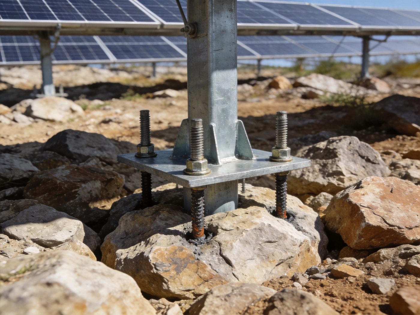
Rock anchoring foundations are the structural solution when solar mounting projects encounter bedrock, shallow rock strata, or hard rock outcrops that make driven piling, ground screw installation, or concrete excavation impractical or structurally inferior — replacing soil-based foundation resistance mechanisms with direct mechanical and chemical bonding to the rock mass through grouted steel anchor rods drilled into the bedrock surface. Rock anchoring systems are specialized solutions within modern solar foundation systems, designed for projects built on bedrock or shallow rock layers where the exceptional compressive and tensile strength of intact rock can be mobilized to resist wind uplift, lateral force, and overturning moment at structural capacities per anchor that far exceed what soil-based foundations achieve at equivalent embedment depth. For a comprehensive overview of all available solar foundation options and the selection criteria that determine when rock anchoring is structurally required versus when soil-based alternatives remain viable, visit our Solar Foundation Systems Guide.
The engineering logic of rock anchor foundations inverts the design approach of all soil-based foundation types: rather than sizing a foundation element to spread the column load over a sufficient soil area to stay within the soil’s allowable bearing capacity, rock anchor design sizes the anchor rod to develop sufficient bond along the rock-grout interface over a relatively short drilled embedment length to resist the full factored load — because intact rock bearing capacity (typically 5,000–50,000 kPa) is 50–500× higher than soil bearing capacity, eliminating the plan area constraint that governs soil foundation sizing and reducing the structural element to a single high-tensile rod in a drilled hole. The result: rock anchor foundations achieve their full structural capacity in 0.5–1.5 m of drilled embedment — less than one-quarter of the embedment required by soil-based foundation types — while delivering wind uplift resistance that exceeds any soil-based alternative at equivalent material cost.
Technical Snapshot: Rock Anchoring Foundation Key Parameters for Solar Mounting
| Parameter | Typical Value / Range | Governing Condition | Engineering Note |
|---|---|---|---|
| Drilled Embedment Depth | 0.5–1.5 m in strong intact rock (UCS > 50 MPa); 1.5–3.0 m in weak or fractured rock (UCS 10–50 MPa); 3.0–5.0 m in very weak rock or heavily jointed rock mass | Rock unconfined compressive strength (UCS); rock mass rating (RMR); joint spacing and orientation; required bond length for design load | Embedment depth in rock is determined by bond length calculation (τbond × π × dhole × Lbond ≥ Tu,factored), not by bearing area or dead weight — a 600 mm embedment in granite (UCS = 150 MPa) with 150 mm hole diameter provides more uplift resistance than a 2.0 m concrete footing in medium soil |
| Anchor Rod Diameter | M24–M36 threaded rod (diameter 24–36 mm) for standard solar mounting applications; M40–M52 for high-load tracker systems in extreme wind zones; 25–32 mm smooth bar with end bearing plate for mechanical anchor type | Design tensile force Tu; bolt grade (Grade 8.8, Grade 10.9, or ASTM F1554 Grade 105); embedment and grout bond length | Anchor rod steel capacity (φFyAb) must be verified against both the required tensile capacity and the combined tension-shear interaction at the anchor head — the governing failure mode switches from steel tensile rupture (short embedment) to grout-rock bond failure (long embedment) depending on rod diameter and grout quality |
| Drilled Borehole Diameter | 51–76 mm for M24–M30 anchors (minimum annular grout space = 12–15 mm per side); 76–102 mm for M36–M52 anchors; 102–150 mm for large-diameter or double-rod anchor assemblies | Anchor rod diameter + minimum annular grout space (12 mm minimum per side per EN 1537; 6 mm minimum per FHWA NHI-99-015) | Annular grout space governs effective grout placement — insufficient annular space prevents complete void filling around the rod and reduces bond length reliability; diamond core drill or rotary percussive drill diameter must be selected to provide the specified annular space after inserting the anchor rod and centralizers |
| Grout Compressive Strength | Cement grout: f’c = 28–42 MPa (Type I/II OPC, w/c = 0.40–0.45) — standard for most rock anchoring applications; Resin (polyester or epoxy): f’c equivalent = 70–100 MPa — faster cure, higher bond strength, preferred where groundwater is present during installation | Rock UCS (grout strength should not exceed rock UCS by more than 2×); installation conditions (groundwater presence governs grout type — resin preferred over cement grout in flowing water); design bond stress τbond required | Grout strength does not linearly control bond capacity — bond failure at the rock-grout interface is governed by the weaker of: (a) grout shear strength; (b) rock surface roughness (clean, rough drill hole wall provides 40–60% higher bond than smooth or dust-contaminated hole); borehole cleaning before grouting is the single most impactful quality control step in rock anchor installation |
| Design Bond Stress (τbond) | Hard rock (UCS > 100 MPa, granite, quartzite): τbond = 1.4–3.5 MPa; Medium rock (UCS 25–100 MPa, limestone, sandstone): τbond = 0.7–2.0 MPa; Weak rock (UCS 5–25 MPa, shale, mudstone): τbond = 0.35–0.8 MPa; values per FHWA NHI-99-015 Table 4-2 and EN 1537:2013 Table C.1 | Rock type and UCS; drill hole roughness; grout type; anchor inclination | Bond stress values in design codes are conservative ASD allowable values including a safety factor of 2.0–3.0 against ultimate bond failure; site-specific pre-production load testing per PTI DC80.3 or EN 1537 is required on >2% of anchors (minimum 3 tests) to verify that assumed τbond is achievable at the specific rock formation |
| Corrosion Protection Class | Class I (single protection — HDG rod or epoxy coating): dry, non-aggressive rock above groundwater table; Class II (double protection — HDG + cement grout encapsulation): permanent anchors below groundwater; Class III (triple protection — duplex rod + grout + HDPE sheath): aggressive groundwater (pH < 5.5 or sulfate > 200 mg/L) or marine spray zone | PTI DC80.3 §5; EN 1537 §8; groundwater aggressiveness; design life (temporary ≤ 2 years, permanent ≥ 25 years) | The anchor head — above the grout column, exposed to atmospheric moisture and UV — is the highest corrosion risk zone; even Class I anchors require stainless steel or hot-dip galvanized bearing plate and nut at the anchor head to prevent preferential corrosion at the most stress-concentrated and most moisture-exposed component |
| Design Service Life | 30–50 years with Class II protection in standard rock; 25–35 years with Class I protection in dry rock above groundwater; >50 years with Class III protection and stainless rod in aggressive environment | Corrosion protection class; groundwater aggressiveness; anchor head exposure condition; grout void-free coverage of rod | Rock anchor service life in solar mounting is less limited by rock deterioration (rock does not corrode) than by anchor rod corrosion at the grout-rock interface or anchor head — the quality of grout placement (void-free, full bond length coverage) is the primary service life determinant; pull-out testing at 5-year intervals is the monitoring protocol for critical permanent anchors |
What Is a Rock Anchoring Foundation for Solar Mounting?
Structural Concept: Drill, Insert, Grout, Bond
A rock anchor foundation transfers all structural loads from the solar mounting system above — wind uplift, wind lateral force, overturning moment, and dead load — directly into the intact rock mass through a bonded steel anchor rod inserted into a drilled borehole and permanently fixed with cement or resin grout. The structural load path is: solar mounting column base plate → bearing plate and nut at anchor head → anchor rod in tension (for uplift) or combined tension-shear (for lateral + uplift) → grout column in bond shear at the grout-rod interface and the grout-rock interface → rock mass in direct bearing and shear. The critical structural interfaces are the two bond zones: (1) Rod-to-grout bond: the deformed surface of the threaded anchor rod develops mechanical interlock and adhesion with the surrounding grout cylinder; failure in this zone produces rod pull-through of the grout column; (2) Grout-to-rock bond: the outer surface of the grout cylinder bonds to the drilled rock wall through a combination of mechanical interlock (grout filling rock surface micro-roughness) and limited adhesion; failure in this zone produces the grout cylinder pulling out of the rock as a unit (grout cone or interface shear failure). Both bond zones must be designed with adequate safety factor: per PTI DC80.3 (Post-Tensioning Institute: Recommendations for Prestressed Rock and Soil Anchors): FS ≥ 2.0 for temporary anchors, FS ≥ 2.5 for permanent anchors against bond failure at each interface. The overall design sequence: (1) determine factored design uplift demand Tu from structural analysis; (2) calculate required anchor rod steel area: Arod ≥ Tu/(φ × Fy); (3) calculate required grout bond length: Lbond ≥ Tu/(π × dhole × τbond,allow × FS); (4) verify that selected embedment depth provides at least Lbond within competent rock (excluding weathered or fractured rock at the top of the rock profile).
Key Components and Materials
A complete rock anchor assembly for solar mounting comprises six components: (1) Drilled borehole: the cylindrical void in rock produced by rotary percussive (air-track drill) or diamond core drilling, at the specified diameter and depth; the borehole wall surface roughness — governed by drill bit type and advance rate — directly controls τbond achievable in the finished anchor; percussion-drilled holes are rougher than diamond-cored holes and develop 20–40% higher bond stress at equivalent rock quality; (2) Steel anchor rod: high-strength threaded steel rod (ASTM F1554 Grade 55, 105, or 150; EN 10025 Grade S460 or S550) providing the tensile structural member; rod diameter selected to provide φArodFy ≥ Tu with the specified bolt grade; rod length = bond length + free-stressing length (if post-tensioned) + above-grade extension to base plate; (3) Centralizers: plastic spacer clips at 600–1,000 mm intervals along the rod length, holding the rod centered in the borehole to ensure minimum annular grout space of 12 mm on all sides — the most commonly omitted component in field installation and the most common cause of inadequate grout coverage; (4) Cement or resin grout: the bonding medium filling the annular space between rod and rock — cement grout (w/c = 0.40–0.45, no admixtures unless anti-bleed is required) for standard conditions; two-component polyester or epoxy resin cartridge grout for installations in water-bearing rock or where early strength (<24 hours) is required; (5) Bearing plate: a steel plate (typically 150×150 mm to 250×250 mm, thickness 20–30 mm) placed at the rock surface against which the anchor nut bears, distributing the anchor load over a contact area rather than concentrating it at the rod cross-section; bearing plate area must be sufficient so that bearing pressure on the rock surface does not exceed the rock’s allowable surface bearing capacity; (6) Anchor nut and washer: heavy-hex nut on the threaded rod above the bearing plate, tightened to the specified proof load (typically 50–70% of FyArod) to pre-compress the bearing plate against the rock surface and eliminate anchor head movement under wind load cycling. Long-term structural integrity of all exposed and embedded metallic components — particularly the anchor head assembly above the grout column — depends on the corrosion protection system specified for the project’s rock environment; the complete corrosion protection specification by exposure class is developed in the foundation corrosion protection resource.
When Engineers Choose Rock Anchoring Over Soil-Based Foundations
Structural engineers specify rock anchoring foundations in three defining site conditions where soil-based foundation types are structurally or logistically inferior: (1) Shallow bedrock or rock outcrop (< 0.5 m depth to rock surface): driven piles cannot be advanced through rock without specialized rock-breaking tips and high-energy hammers; ground screws cannot penetrate rock regardless of torque input; concrete footings require excavation into rock (expensive blasting or hydraulic hammer) to achieve frost-depth embedment; rock anchoring directly exploits the rock surface without requiring any removal of rock material — a drilled anchor in 500 mm of intact granite achieves greater uplift resistance than a 2.0 m concrete footing in medium soil at a fraction of the excavation cost; (2) Mountain, ridge, and high-elevation solar sites: topographic wind acceleration at ridge and mountain sites (topographic factor Kzt > 1.0–1.8 per ASCE 7-22 Chapter 26) dramatically increases design wind pressure and foundation uplift demand; simultaneously, these sites typically have shallow soil over bedrock — the combination of high uplift demand and shallow soil makes rock anchoring the only structurally viable foundation type at many mountain solar projects; (3) Sites where construction equipment access favors light drilling over heavy foundation equipment: remote mountain or ridge solar sites accessible only by narrow access road or helicopter cannot receive the heavy pile driving rigs, concrete mixer trucks, or excavator equipment required for conventional foundation types; a pneumatic air-track drill and a compressor can be transported to sites that are inaccessible to conventional foundation equipment, making rock anchoring the only practically installable foundation type at remote high-elevation locations. The load transfer mechanism that distinguishes rock anchor structural behavior from pile and screw foundations — grout bond stress mobilization versus skin friction and helix bearing — is explained in the load transfer principles resource; the geological investigation methodology for characterizing rock mass quality and selecting design bond stress values is in the geotechnical site analysis resource.
Video: solar ground screw pile installation.
Engineering Principles Behind Rock Anchor Foundations
Bond Strength Between Anchor Rod, Grout, and Rock: The Governing Capacity Mechanism
Rock anchor uplift capacity is governed by the weaker of two bond interfaces in series: (1) Rod-to-grout interface: bond stress τrg at the deformed rod surface against the surrounding grout; for a deformed threaded rod (thread height ≈ 1.5–2.0 mm), the rod-grout bond is primarily mechanical interlock rather than adhesion; allowable τrg ≈ 0.03–0.10 × f’c,grout (ACI 318-19 Chapter 25 development length basis) — for f’c,grout = 35 MPa: τrg,allow ≈ 1.05–3.5 MPa; required bond length to develop full rod tensile capacity: Ldev,rod = FyArod/(π × drod × τrg,allow); (2) Grout-to-rock interface: bond stress τgr at the outer grout cylinder surface against the drilled rock wall; this interface governs overall anchor capacity in most practical rock anchor designs because the drilled hole surface, even in hard rock, provides lower unit bond stress than the deformed rod-grout interface; design τgr values from FHWA and PTI tables (as listed in the Technical Snapshot) range from 0.35 MPa in weak rock to 3.5 MPa in hard intact rock; required grout bond length: Lbond = Tu,factored/(π × dhole × τgr,allow). Design example: M30 anchor rod (Fy = 640 MPa, Arod = 561 mm²) in medium limestone (UCS = 40 MPa, τgr,allow = 1.2 MPa) with 76 mm hole diameter: Tu,steel = 0.75 × 640 × 561/1,000 = 269 kN; Lbond,req = 269,000/(π × 76 × 1.2) = 269,000/286.5 = 939 mm ≈ 1.0 m. A 1.0 m embedment in medium limestone with 76 mm drill hole achieves 269 kN allowable uplift — more than sufficient for any standard solar mounting column in all but the most extreme coastal wind environments.
Axial Tension Capacity and Safety Factor Requirements
Axial tension capacity of a rock anchor must be verified against three sequential failure modes, each with its own governing equation and required safety factor per PTI DC80.3: (1) Steel rod yielding or fracture: Tallow,steel = φt × Fy × Arod where φt = 0.75 (LRFD) or FS = 1.67 (ASD) — this is the upper bound capacity; anchor rod must not be under-sized relative to the factored demand; (2) Grout-rock interface bond failure: Tallow,gr = τgr,allow × π × dhole × Lbond with τgr,allow = τgr,ult/FSbond (FSbond = 2.5 for permanent anchors per PTI); this typically governs anchor length; (3) Rock mass cone failure (group uplift): where multiple anchors are spaced closely, the rock cone of influence for each anchor overlaps adjacent cones — group capacity must be checked by treating the anchor group as a monolithic block with the failure surface as a truncated cone through the rock mass; cone failure capacity = weight of rock cone + shear resistance on cone surface = rarely governs for properly spaced solar mounting anchors at standard spacings of 2.0–6.0 m, but must be checked at very close anchor spacing (< 2 × embedment depth). Anchor spacing governs group effects: anchors spaced ≥ 3 × embedment depth (Lbond) apart develop fully independent cone failure surfaces — the standard design target for solar mounting anchor layout. For a complete treatment of all foundation capacity verification methodologies and their comparison across pile, screw, concrete, and rock anchor types, refer to the complete solar foundation guide.
Shear Resistance in Rock Mass: Lateral Load Transfer
Lateral load resistance of rock anchor foundations — resisting wind horizontal force at the column base — is provided by three mechanisms acting at the anchor-rock interface: (1) Anchor rod bending and shear: the anchor rod acts as a short cantilever embedded in rock, developing bending resistance at the rock surface as the column base plate applies lateral force at the anchor head; the anchor rod must be checked for combined tension (from uplift) + shear (from lateral) + bending (from eccentricity at bearing plate) using the tension-shear interaction equation per AISC 360-22 Chapter J: (Tu/φTn)² + (Vu/φVn)² ≤ 1.0; (2) Bearing plate friction on rock surface: if the bearing plate is pre-tensioned against the rock surface with a defined proof load Ppre, the friction resistance = µ × Ppre (where µ = 0.5–0.7 for steel-on-rough-rock); pre-tensioning the anchor provides passive lateral resistance without requiring lateral deformation; (3) Rock surface passive resistance: the bearing plate edge and column base pedestal (if any) bear against the rock surface under lateral load, developing passive rock bearing resistance that supplements anchor rod shear capacity. In high-wind mountain applications where lateral force exceeds the anchor rod shear capacity from vertical anchors alone, inclined anchors (drilled at 15–30° from vertical, inclined into the direction of the dominant lateral wind force) mobilize an axial tension component that resists lateral load more efficiently than vertical anchor shear.
Grout–Rock Interaction Mechanics: Interface Development and Failure Modes
The mechanics of grout-rock bond development determine the reliability and safety factor available at the governing interface in rock anchor design. Grout fills the annular space between anchor rod and rock wall, creating a composite cylinder that bonds to the rock wall through three mechanisms: (1) Chemical adhesion: cement hydration products (calcium silicate hydrate, portlandite) chemically bond to the silica surface of most rock types; adhesion contributes τadhesion ≈ 0.1–0.3 MPa in intact rock — a minor component that is explicitly neglected in most design codes for conservatism; (2) Mechanical interlock: fresh grout penetrates micro-cracks and surface irregularities on the drilled rock wall and hardens in place, creating mechanical keys that resist shear displacement at the grout-rock interface; mechanical interlock is the dominant bond mechanism and is directly proportional to the surface roughness of the drilled hole — percussion drilling creates a rougher hole surface than diamond coring and develops 20–40% higher τbond; (3) Friction under normal stress: when the grout column is loaded in shear, Poisson expansion of the grout creates lateral normal stress against the rock wall that generates friction resistance; this dilatancy effect increases τbond under high confinement (deep embedment) relative to shallow embedment. The critical construction quality control implication: a drill hole with dust or water film on the wall before grouting can reduce τbond by 50–70% relative to a clean, rough hole — making borehole cleaning (compressed air flush followed by water flush for cement grout; dry compressed air only for resin grout) the single highest-impact installation quality step in rock anchor construction.
Structural Anatomy & Cross-Section Breakdown
Drilled Borehole Geometry: Diameter, Depth, and Inclination
Borehole geometry specification encompasses three parameters: (1) Diameter: governed by anchor rod diameter plus required annular grout space; minimum annular space = 12 mm per side (EN 1537) or 6 mm per side (FHWA minimum — not recommended for quality grout placement); practical recommendation: 25 mm annular space per side for cement grout (providing adequate space for tremie-tube grouting without plug formation); 15 mm annular space per side acceptable for resin cartridge grout (resin is more viscous but does not require tremie tube); therefore, for a M30 anchor rod (30 mm OD): recommended hole diameter = 30 + 2×25 = 80 mm → specify 76 mm nominal drill size as standard tooling; (2) Depth: total drill depth = weathered/fractured zone depth at rock surface (excluded from bond length calculation) + required grout bond length Lbond + 50–100 mm sump at drill bottom for drill cuttings; total depth for 1.0 m bond length in fresh rock with 200 mm weathered zone: 1.0 + 0.2 + 0.1 = 1.3 m total drill depth; (3) Inclination: vertical (90° from horizontal) is standard for solar mounting anchors resisting primarily vertical uplift; inclined at 15–30° from vertical (inclined toward the dominant upwind direction) is used in high-wind sites where lateral force magnitude is comparable to uplift force — inclined anchors develop an axial tension component (F × cos θ for uplift, F × sin θ for lateral) that mobilizes the full anchor rod tensile capacity for the combined load vector, more efficiently than vertical anchors where lateral force must be resisted by bending + shear in the rod.
Grouting Technique: Tremie Tube vs Cartridge vs Pressure Grouting
Three grouting techniques are used for solar mounting rock anchors, each suited to specific borehole orientation and groundwater conditions: (1) Tremie tube (upstage) cement grouting: a thin grout tube (12–19 mm OD) is inserted to the bottom of the borehole alongside the anchor rod; grout is pumped from the bottom of the hole upward, displacing air out the top of the borehole; the tremie tube is withdrawn progressively as the grout level rises; this method provides the most reliable void-free grout placement in dry to damp boreholes and is the standard method for permanent solar mounting anchors in non-flowing groundwater; (2) Resin cartridge grouting: pre-packaged two-component polyester or epoxy resin cartridges (50–100 mm diameter, 150–500 mm length) are inserted into the borehole to fill the required bond length zone; the anchor rod is then inserted through the cartridges with a rotation that ruptures the inner membrane and mixes the two components; resin catalyzes and hardens within 5–60 minutes (temperature-dependent); this method is preferred for boreholes with active groundwater flow (water washing cement grout from the borehole), for fast-cycle installation, and for horizontal or upward-inclined boreholes where cement grout cannot be gravity-tremied; (3) Pressure (stage) grouting: cement grout pumped under pressure (typically 0.1–0.5 MPa above hydrostatic) into the sealed borehole, forcing grout into rock fissures adjacent to the borehole wall and significantly enhancing τbond by increasing the effective bond surface area beyond the nominal drilled hole perimeter; used in fractured rock where natural fissures provide additional grout penetration paths; increases τbond by 30–80% over gravity tremie grouting in fractured rock formations. Mountain and high-elevation solar sites experience freeze-thaw cycling that acts on both the exposed anchor head assembly and on the upper section of the grout column — the thermal cycling design implications for anchor head assembly specification and grout cover depth are addressed in the frost protection design resource.
Anchor Rod Specification: Grade, Diameter, and Thread Form
Anchor rod specification for solar mounting rock anchors requires three decisions: (1) Steel grade: ASTM F1554 Grade 36 (Fy = 248 MPa) is the minimum standard for non-structural applications but is under-specified for solar mounting anchor rods — Grade 55 (Fy = 380 MPa) is the standard commercial specification for solar mounting; Grade 105 (Fy = 724 MPa) is used in high-wind or seismic extreme sites where higher rod tensile capacity allows smaller rod diameter at equivalent load, reducing drill hole diameter and installation cost; (2) Thread form: coarse unified thread (UNC) for standard galvanized rods — provides mechanical interlock with grout, contributing to rod-grout bond; continuous threaded rod (fully threaded over full length) is preferred over partially threaded rod (smooth shank below the threaded engagement length) for grouted anchors because continuous thread provides bond over the entire bond length; (3) Corrosion protection on rod surface: hot-dip galvanizing (HDG) per ASTM A153 for anchors in non-aggressive dry rock above groundwater (Class I); fusion-bonded epoxy (FBE) coat over HDG for anchors in wet or mildly aggressive rock (Class II); solid stainless steel rod AISI 316 for anchors in aggressive groundwater (sulfate, chloride, low pH) or marine spray zone (Class III); the corrosion protection specification on the anchor rod must be compatible with the grout type — epoxy-coated rods should use epoxy resin grout rather than cement grout to ensure adhesive compatibility at the rod-grout interface.
Connection Interface to Solar Mounting System
The anchor head connection to the solar mounting racking system is the structural interface that receives all column base loads and transfers them into the anchor rod. Three connection configurations are used: (1) Direct threaded column base: the anchor rod threads directly into a threaded receptacle in the solar mounting column base — used for standardized column base designs where anchor pattern matches the column base template exactly; requires precise anchor installation tolerance (±5 mm plan position, ±0.5° vertical alignment); any misalignment discovered after grout hardening cannot be corrected; (2) Bearing plate with leveling nuts: the standard configuration — a square or round steel bearing plate (150–250 mm, 20–30 mm thick) with anchor rod passing through a central hole; a lower leveling nut sets the exact bearing plate elevation; upper nut locks the assembly; the column base plate rests on the bearing plate or on separate leveling bolts bearing against the bearing plate; this configuration accommodates ±10–15 mm horizontal misalignment through slotted holes in the column base plate and ±20–30 mm elevation variation through leveling nut adjustment; (3) Cast-in epoxy anchor with anchor plate template: the borehole is drilled, cleaned, and injected with epoxy grout; an anchor bolt template holding the bolts at the exact column base plate pattern is inserted into the fresh epoxy and held plumb and at the correct elevation until the epoxy cures (15–60 minutes for fast-set epoxy); this produces the most precise anchor pattern alignment and is preferred where column base plate cannot accommodate misalignment adjustment.
Installation Workflow
Phase 1 — Geological Survey, Rock Mass Characterization, and Core Sampling
Pre-installation geological investigation for rock anchoring foundations is more specialized than the standard SPT-based investigation used for soil foundations — and is the most frequently under-resourced phase in rock anchor solar projects, leading to post-installation capacity surprises. Required geological deliverables before drilling design is finalized: (1) Rock mass classification: Rock Mass Rating (RMR per Bieniawski 1989) or Q-system (Barton et al.) assessment from surface mapping and borehole core inspection; RMR ≥ 60 (Good rock) confirms that design τbond values from code tables are applicable without site-specific reduction; RMR 40–60 (Fair rock) requires conservative τbond selection and mandates pre-production pull-out testing; RMR < 40 (Poor or Very Poor rock) requires site-specific load testing before any production anchor installation; (2) Unconfined compressive strength testing: laboratory UCS tests on rock core samples (minimum 5 samples from the embedment zone per rock formation type); UCS confirms the rock type classification for τbond selection from FHWA or PTI tables; (3) Joint orientation mapping: the orientation of rock joints (bedding planes, foliation, fractures) relative to the anchor axis governs whether the anchor bond length crosses joint planes — anchors crossing favorably oriented joints (perpendicular to anchor axis) mobilize full bond along the full bond length; anchors crossing adversely oriented joints (parallel to anchor axis) may have reduced effective bond area where the joint plane intersects the borehole; (4) Groundwater assessment: groundwater presence in the drilling zone affects grout type selection (cement vs resin) and corrosion protection class; standing water in boreholes at time of grouting requires either water pumping before cement grouting or automatic selection of resin grout, which is water-insensitive during cure. The foundation selection guide provides the integrated decision framework for determining when geological conditions warrant rock anchoring over soil-based alternatives, and documents the investigation scope required to confirm rock anchor viability before project commitment.
Phase 2 — Drilling, Anchor Insertion, and Grouting Operations
Rock anchor installation sequence for solar mounting: (1) Survey layout: anchor positions marked at ±10 mm plan tolerance from design coordinates; borehole inclination template set to design angle (90° for vertical; specified angle for inclined anchors); (2) Drilling: rotary percussive (air-track) drilling is standard — drill advances with combined rotation and impact; drill cuttings flushed from hole with compressed air; drill depth confirmed at or below target by rod count; (3) Borehole cleaning: compressed air flush at minimum 0.7 MPa pressure for minimum 30 seconds after drilling completion to remove all drill cuttings and dust from the borehole wall; water flush (for cement grout) or dry air only (for resin grout) follows compressed air to clean borehole wall and pre-wet rock surface for cement grout hydration; inspect borehole with flashlight or borehole camera to confirm cleanliness before anchor insertion — this inspection is mandatory and is the QC step most frequently omitted under schedule pressure; (4) Anchor insertion: centralizers attached to anchor rod at 600–1,000 mm spacing; tremie tube (for cement grout) taped to rod alongside; rod-and-tube assembly lowered to bottom of borehole; rod alignment confirmed plumb (±0.5° from design inclination) using digital inclinometer on rod; (5) Grouting: grout pumped through tremie tube from bottom upward; tremie tube withdrawn as grout level rises, maintaining tremie tip submerged in grout at all times to prevent air entrapment; grout volume pumped and returned from top of hole recorded — volume less than theoretical borehole volume indicates incomplete filling and requires investigation (possible loss into rock fissures — increase grout volume; possible bridging — re-drill and re-grout); (6) Cure: cement grout requires minimum 7 days before load application; resin grout requires 1–24 hours depending on formulation and temperature; do not apply any load (including erection loading) before specified cure time.
Phase 3 — Pull-Out Testing, Grouting Verification, and Structural Acceptance
Rock anchor acceptance testing per PTI DC80.3 requires three test types: (1) Pre-production (investigation) tests: minimum 3 anchors tested to failure (or 80% of grout bond capacity) before production installation begins; tests confirm site-specific τbond at the actual rock formation and grout type, allowing the Kbond safety factor to be calibrated against measured rather than tabulated values; pre-production tests are required when design τbond exceeds 50% of the code table value, when RMR < 60, or when project total anchor count exceeds 100; (2) Proof (performance) tests: 5% of all production anchors tested to 133% of the design load; anchor passes if creep (movement under sustained test load) is < 1.0 mm over the 10-minute sustained load hold at 133% design load; (3) Lift-off (verification) tests: for post-tensioned anchors only — a flat-jack hydraulic ram confirms that the applied pre-tension remains within ±5% of the specified lock-off load after grout cure. Post-installation structural inspection: grout return volume verified for each anchor (total grout pumped versus theoretical borehole volume); bearing plate contact against rock surface confirmed (no gap visible); nut tightening confirmed at proof load; anchor head protection cap installed.
Worked Rock-Anchor Bond-Length Example
This example shows the calculation sequence, not a reusable construction dimension. Assume the design tensile demand transferred into competent rock is 72 kN, the drilled hole diameter is 90 mm, and the project-specific design grout-to-rock bond resistance established for preliminary sizing is 0.25 MPa.
Required bonded length: L = T / (π × dhole × τdesign) = 72,000 / (π × 0.09 × 250,000) ≈ 1.02 m. Adding a 25% construction allowance gives about 1.28 m, so a preliminary 1.3 m bond length inside competent rock could be carried into the test program.
| Independent check | Required evidence | Why the bond calculation is not enough |
|---|---|---|
| Anchor steel | Rod area, grade, thread reduction, combined tension/shear and corrosion allowance | The rod or threaded section may govern before the grout bond |
| Grout-to-rod bond | Thread profile, grout strength, annulus and installation method | The inner bond interface can fail even if the rock interface passes |
| Rock mass | Core log, discontinuities, weathered-zone depth, rock cone or block stability | A sound borehole wall does not guarantee the surrounding rock block is stable |
| Proof/load testing | Test load, hold period, movement limits, calibration and acceptance record | Testing validates the assumed design bond resistance and construction process |
| Durability | Groundwater chemistry, grout cover, anchor-head sealing and inspection access | Section loss or water ingress can control long-term capacity |
If test anchors do not satisfy the project acceptance criteria, revise the bond resistance, length, diameter or installation method before production drilling. Do not average a weak geological zone into stronger test results.
Performance Analysis
Wind Load Resistance in Rocky and Mountain Terrain
Wind load on solar arrays in rocky mountain and ridge terrain is dramatically higher than on flat open terrain at equivalent wind speed — ASCE 7-22 Chapter 26 topographic factor Kzt applies a wind pressure amplification of 1.0–3.24 (up to 3.24× increase in velocity pressure) for isolated hills, ridges, and escarpments with height-to-base-width ratios H/Lh ≥ 0.5. At the crest of a steep ridge (Kzt = 1.69 for K1 = 0.5, K2 = 1.0, K3 = 1.0): wind velocity pressure qz = 0.00256 × Kz × Kzt × V² = 0.00256 × 0.93 × 1.69 × 115² = 59.1 psf = 2.83 kPa — compared to 1.38 kPa on flat open terrain at the same wind speed; a 2.05× amplification that nearly doubles design uplift forces and anchor demand relative to a flat-site calculation. Rock anchor foundations in mountain terrain are structurally well-matched to this elevated demand: the same bedrock that forces the use of rock anchors (shallow soil over rock) provides the high-strength rock matrix (UCS ≥ 50–150 MPa for typical granite and quartzite ridge geology) that supports the highest τbond design values in the FHWA table. Rock anchor design in mountain terrain therefore has the favorable characteristic that the geological condition driving the use of rock anchors (hard bedrock at shallow depth) simultaneously provides the highest available anchor capacity — a structural alignment that makes rock anchors the optimal foundation type, not merely the only viable one, in strong-rock mountain environments. The complete wind pressure calculation methodology for topographically complex terrain — including the ridge and hill Kzt factor calculation procedure — is in the wind load calculation standards resource.
Snow Load and Mountain Climate Impact
Mountain solar sites experience ground snow loads pg substantially higher than the flat-terrain snow loads at equivalent latitude — ASCE 7-22 Figure 7.2-1 shows that pg in mountainous areas of the western United States (Sierra Nevada, Rocky Mountains, Cascades) frequently exceeds 2.0–5.0 kPa (40–100 psf) at elevations above 1,500–2,500 m, versus 0.5–1.0 kPa for coastal and valley areas at equivalent latitude. Snow load adds axial compression to rock anchors (favorable for compressive bearing on rock surface, unfavorable only if the anchor is designed for tension-only capacity without compression-bearing hardware). The critical snow-related design consideration for rock anchor solar at mountain sites is the asymmetric snow accumulation pattern: solar panels accumulate snow on the south-facing surface that sheds as a concentrated sliding mass to the front (north-facing downslope row) of the array, creating a dynamic impact load on the front row structure that adds to the normal uplift and lateral design demands on the front-row anchors. This asymmetric snow shedding load — typically not included in standard wind-only anchor design — must be included in the front-row anchor demand calculation at high-snow mountain sites.
Long-Term Corrosion Durability: Anchor Rod and Grout Interface
Rock anchor corrosion performance over the 30–50-year design life specified for permanent solar installations depends on two independent corrosion zones that require separate management: (1) Below-grout zone (embedded anchor rod): the anchor rod within the cement or resin grout column is protected by both the coating on the rod and the grout encapsulation; void-free grout of adequate cover thickness (≥ 25 mm from rod surface to borehole wall) maintains a high-pH, low-oxygen environment around the steel that severely retards corrosion; defects in grout cover (voids, shrinkage cracks, incomplete filling) allow groundwater to reach the anchor rod surface and initiate crevice corrosion at the confinement of the rock-grout interface — the most dangerous corrosion mode because it is invisible and progressive; (2) Anchor head zone (above grout, exposed to atmosphere or shallow soil): the bearing plate, nut, washer, and anchor rod above the grout column are exposed to atmospheric oxygen, UV, moisture, and in mountain environments, freeze-thaw cycling and de-icing chemicals from winter road maintenance; this zone requires the highest corrosion protection specification — HDG bearing plate and nut, stainless steel washers, anchor head protection cap over the nut. Grout void detection at the time of installation — by verifying that the theoretical borehole grout volume matches the actual volume pumped — is the primary construction control against embedded corrosion defects; post-installation ultrasonic pulse velocity testing of the grout column can detect major voids in accessible boreholes as supplementary verification.
Seismic Stability in Rock Formations
Rock anchor foundations in seismic zones perform differently from soil-based foundations under earthquake loading because the seismic response of a rock-anchored structure is governed by rock mass stiffness rather than soil stiffness — and rock is 10–100× stiffer than soil, resulting in fundamentally different seismic demand on the anchor-structure system. Three seismic considerations specific to rock anchor solar foundations: (1) Short-period amplification: stiff rock sites (Site Class A or B per ASCE 7-22 §20.3) have lower seismic site amplification factors Fa and Fv than soft soil sites — the short-period design spectral acceleration SDS on rock is typically 20–40% lower than the same site on soft soil, reducing seismic design forces on the foundation; (2) Rock mass joint behavior under seismic shaking: rock joints (fractures, bedding planes) in the anchor bond zone can be temporarily opened by seismic dynamic stress, reducing the effective τbond momentarily during peak shaking; anchors in heavily fractured rock (RMR < 40) at SDC D–F sites require seismic uplift demand amplified by Ω0 (overstrength factor = 2.0–3.0) at the anchor head connection per ASCE 7-22 §12.3.3.3; (3) Rock slope stability: seismic loading adds an inertial lateral force to the rock slope above and below the solar array — ASCE 7-22 Chapter 11 seismic demand combined with static factor of safety on rock slope stability must be verified where the array is founded on a steep rock slope (inclination > 25°). The complete seismic design framework for solar mounting structures — including the site class determination, anchor connection demand amplification, and slope stability assessment procedures — is in the seismic design considerations resource.
Advantages & Limitations
Structural and Commercial Advantages
- Ideal for sites where shallow rock makes soil-based foundations impractical: rock at < 0.5 m depth defeats driven piles (cannot be driven), ground screws (cannot penetrate), and concrete footings (require expensive rock excavation); rock anchoring directly exploits the bedrock that blocks other foundation types, achieving full design capacity in 0.5–1.5 m drilled embedment at lower material cost than any of the alternatives
- Highest available uplift resistance per anchor at equivalent embedment depth: rock bond stress values (0.7–3.5 MPa design allowable) are 10–70× higher than soil bearing capacity for equivalent foundation plan area — a single M30 anchor in granite achieves 150–250 kN allowable uplift in 0.8 m of embedment; an equivalent uplift resistance in medium soil requires a 600 mm diameter concrete drilled shaft to 3.0 m depth with full reinforcing — at 5–8× the material cost per foundation position
- Lightweight installation equipment accessible to remote mountain sites: pneumatic air-track drill (transport weight 800–2,000 kg) plus portable air compressor accesses sites by narrow access road, ATV trail, or helicopter sling load that are completely inaccessible to pile driving rigs (15–35 tonnes), concrete mixer trucks, or crane-assisted foundation equipment
- Long structural service life in non-aggressive rock: properly installed Class II rock anchors in standard rock above groundwater achieve 30–50 year structural service life — the longest of any solar foundation type except concrete — because once the grout is fully cured and void-free, the embedded anchor rod is protected by grout encapsulation from the groundwater and oxygen that drive metallic corrosion
- Reversible and repeatable for project extensions: rock anchors can be de-tensioned and the rod withdrawn from the borehole if the grout bond is broken by hydraulic fracture — leaving a 50–80 mm hole in the rock that can be re-grouted and re-anchored for a replacement installation; or the borehole can be permanently grouted closed after rod removal for complete site restoration (smaller residual impact than any concrete or pile foundation type)
Structural and Commercial Limitations
- High drilling cost in hard rock — the dominant cost variable: rock drilling cost scales with rock hardness (UCS), drill diameter, and depth; in granite (UCS = 150–200 MPa), a 76 mm hole to 1.5 m depth costs $80–$200 per anchor including drill rig time and bit wear — compared to $8–$15 per ground screw installation in soft soil at equivalent structural demand; for large-scale utility solar on hard granite terrain, drilling cost alone can exceed the entire foundation cost for an equivalent project on moderate soil
- Requires competent rock at accessible depth — not applicable to deep soil over weak rock: rock anchors require rock with RMR ≥ 40 (Fair rock minimum) at a depth accessible by drill equipment; deeply weathered rock profiles (10–30 m of completely weathered rock above fresh bedrock, common in tropical and subtropical climates) present a zone too deep for cost-effective anchoring and with τbond values too low for standard anchor design; in these profiles, driven piles or ground screws into the weathered zone are structurally and commercially preferred
- Pre-production load testing required — adds cost and schedule in fractured rock: in RMR < 60 rock (Fair to Poor quality), pre-production pull-out testing is mandatory before production installation to verify site-specific τbond; testing mobilization, equipment, and reporting adds $15,000–$40,000 and 2–3 weeks to project pre-construction schedule — a significant soft cost for small-to-medium solar projects that cannot be amortized over large anchor quantities
- Low removal flexibility — extraction is costly or impractical in some rock formations: in very hard granite or quartzite, hydraulic de-bonding for rod extraction is only partially effective; the grout column may be too strong to de-bond and the rod must be cut at the rock surface, leaving the bonded portion permanently in the rock; for land restoration requirements that prohibit any below-surface residual material, rock anchors may not satisfy the environmental remediation specification
Best Application Scenarios
Mountain Solar Farms: High Elevation, Steep Terrain, Shallow Rock
Mountain solar farms at elevations of 1,500–4,000 m — increasingly common in Europe (Alps, Pyrenees), Asia (Himalayas, Andes, Tibetan Plateau), and North America (Rocky Mountains, Sierra Nevada) as developers seek unshaded south-facing slopes with high solar irradiance — are the primary application environment where rock anchoring is not merely preferable but structurally mandatory. The combination of bedrock at <0.5 m depth (preventing all other foundation types), topographic wind amplification (Kzt = 1.4–2.5 at ridge crests), extreme snow loads, seismic exposure, and limited equipment access defines a structural and logistical environment that rock anchors are uniquely capable of resolving. For the complete engineering design framework for utility-scale solar projects across all terrain types — including the specific structural adaptations required for mountain terrain solar versus flat-land utility scale — the utility-scale solar resource provides the application engineering reference.
Desert Rocky Terrain: Hard Caliche, Desert Pavement, and Basalt
Arid desert regions — American Southwest, Middle East, Atacama, Australian Outback — frequently present dense caliche hardpan (calcium carbonate cemented soil layer, UCS 5–30 MPa), desert pavement (surface layer of densely compacted angular rock fragments), or basalt lava flows (UCS 50–300 MPa) at shallow depth that defeat driven pile installation and ground screw advancement beyond the hardpan. In these geologies, rock anchoring into the caliche or basalt layer provides a cost-effective solution: τbond in caliche (5–15 MPa UCS) = 0.35–0.8 MPa allowable — sufficient for standard solar mounting anchor demand at 0.8–1.2 m embedment; τbond in basalt (UCS 100–300 MPa) = 1.5–3.5 MPa — the highest available bond stress in any geological formation, enabling extremely short embedment depths and fast drill cycles. Desert rock anchor installations benefit from the dry conditions (low groundwater, low corrosion risk) that allow Class I corrosion protection (standard HDG) to achieve full design service life without supplementary coatings.
High-Wind Ridge Installations: Topographic Amplification Zones
Wind energy developers have established that exposed ridge and escarpment sites experience systematically higher wind speeds than the surrounding terrain — the same topographic amplification that the ASCE 7-22 Kzt factor quantifies for structural design. Solar developers are increasingly co-locating solar arrays at high-wind ridge sites where the combination of high solar irradiance (reduced atmospheric path length at elevation) and available land produces excellent solar yield despite the structural challenges. At these sites, the Kzt amplification of design uplift forces to 1.5–2.0× the flat-terrain equivalent, combined with bedrock at shallow depth, makes rock anchoring the only structurally viable and economically justifiable foundation type — soil-based foundations at 2× uplift demand in shallow soil have insufficient mass and depth to resist the design loads, whereas rock anchors in the hard bedrock that creates the ridge topography achieve the amplified demand with standard embedment depths.
Cost & ROI Considerations
Rock anchor foundation cost is dominated by drilling cost — unlike all other solar foundation types where the dominant cost is the structural element itself (pile section, screw hardware, or concrete and rebar). Drilling cost in rock is a function of rock hardness (UCS), drill diameter, and depth, and varies dramatically between soft caliche (fast, low-bit-wear drilling) and hard granite (slow, high-bit-wear drilling). Typical cost breakdown for a 1 MWp mountain solar installation (approximately 200 foundations) on hard granite (UCS = 150 MPa):
| Cost Component | Unit Cost | Total at 200 Anchors | $/Wp |
|---|---|---|---|
| Drilling (76 mm diameter × 1.5 m depth, hard granite, percussion drill) | $120–$200/anchor | $24,000–$40,000 | $0.024–$0.040 |
| Anchor rod assembly (M30 Grade F1554-105, HDG, 2.0 m length including above-grade) | $45–$65/anchor | $9,000–$13,000 | $0.009–$0.013 |
| Grout material (cement grout, 76 mm hole × 1.5 m, 0.004 m³/anchor) | $8–$12/anchor | $1,600–$2,400 | $0.002 |
| Bearing plate, nut, washer, centralizers, protection cap | $35–$55/anchor | $7,000–$11,000 | $0.007–$0.011 |
| Pre-production pull-out testing (3 tests) | $6,000–$10,000 total | $6,000–$10,000 | $0.006–$0.010 |
| Geological investigation (core samples, RMR classification) | $12,000–$20,000 total | $12,000–$20,000 | $0.012–$0.020 |
| Total rock anchor foundation cost (hard granite) | $300–$480/anchor | $59,600–$96,400 | $0.060–$0.096/Wp |
At $0.060–$0.096/Wp, rock anchor foundations in hard granite are the highest-cost solar foundation type at comparable project scale — but this comparison is structurally irrelevant at mountain rock sites where no other foundation type is viable. The commercially meaningful comparison at rock sites is between rock anchoring (viable) and the alternative of not building the project (infeasible soil conditions). In soft caliche or weak rock (UCS 10–30 MPa), drilling cost reduces to $40–$80/anchor, bringing total rock anchor cost to $0.025–$0.045/Wp — competitive with concrete foundations and justified by the structural performance in challenging terrain. For a cross-site cost analysis comparing rock anchoring to all foundation types across different geological conditions, see the foundation cost comparison resource; for the structural comparison between rock anchoring and concrete footing on mixed rock-soil sites where both are viable, see the pile vs concrete comparison.
Comparative Engineering Matrix
| Criterion | Rock Anchor | Pile Driven | Concrete | Ground Screw |
|---|---|---|---|---|
| Required Ground Condition | ✅ Rock only — optimal in hard bedrock | Soil (N = 5–50); rock requires special tip | Soil or rock (excavation required) | Soil (N = 5–40); rock requires pre-drill |
| Uplift Resistance per Unit Cost | ✅ Very High — rock bond 10–70× soil bearing | High — skin friction + end bearing | Very High — dead weight + passive pressure | Medium — helix bearing in soil |
| CapEx ($/anchor at 1 MWp mountain scale) | $300–$480 in hard rock; $130–$200 in soft rock | $45–$85 in standard soil | $120–$200 in standard soil | $66–$94 in standard soil |
| Installation Speed | Medium — 20–40 anchors/day/drill rig in hard rock; 50–80 in soft rock | Fast — 200–500/day | Slow — 10–21 day cure | Very Fast — 150–400/day |
| Equipment for Remote Mountain Access | ✅ Light — drill rig 800–2,000 kg | ❌ Heavy — 15–35 tonne rig | ❌ Heavy — concrete truck + excavator | Medium — skid-steer rig 3–8 tonnes |
| Wind Resistance in High Kzt Terrain | ✅ Very High — rock bond capacity matches elevated demand | Medium — limited by soil capacity at elevation | Very High — but excavation cost prohibitive in rock | Medium — limited in rocky terrain |
| Seismic Performance in Rock | ✅ High — stiff rock site reduces seismic demand | Variable — soil amplification may increase demand | Very High — mass provides inertial resistance | Medium — limited by soil-structure stiffness |
| Removal Flexibility | Low — extraction difficult in hard rock | Medium — crane extraction possible | ❌ Low — demolition required | ✅ High — reverse torque extraction |
Rock anchors occupy a structurally unique position in the solar foundation ecosystem — they are both the highest-performance foundation type in strong rock and the only viable option at rocky mountain and ridge sites where no other foundation type can be installed. For a complete side-by-side evaluation of all five foundation types across soil condition, wind exposure, climate, and project scale, refer to our Solar Foundation Systems Guide.
Engineering Design Checklist
- Rock core sample retrieved and classified: minimum 5 UCS test specimens from the anchor bond zone per rock formation type; Rock Mass Rating (RMR) calculated from core inspection, joint mapping, and groundwater observation; design τbond selected from FHWA NHI-99-015 Table 4-2 or EN 1537 Table C.1 using the lower-bound UCS from laboratory test results, not the average — conservative selection is mandatory when pre-production testing has not yet confirmed site-specific bond values
- Required grout bond length calculated and verified against available competent rock depth: Lbond = Tu,factored / (π × dhole × τbond,allow) calculated for the governing anchor zone (corner or perimeter); weathered and fractured rock at the top of the rock profile excluded from bond length; confirmed that competent rock depth below the weathered zone is ≥ Lbond + 100 mm sump at all anchor locations
- Anchor rod steel capacity verified against combined tension-shear interaction: (Tu/φTn)² + (Vu/φVn)² ≤ 1.0 per AISC 360-22 Chapter J; tension demand Tu from wind uplift combination (0.9D + 1.0W); shear demand Vu from lateral wind force; interaction check performed at governing anchor zone with combined uplift + lateral loading — not separately maximized for each
- Corrosion protection class specified based on groundwater and rock chemistry: groundwater presence in borehole confirmed by observation during drilling; soil/groundwater pH, sulfate, and chloride from geochemical analysis; corrosion class assigned per PTI DC80.3 §5 (Class I / II / III); specification confirmed in procurement documents before anchor hardware is ordered — post-procurement corrosion specification change requires complete anchor hardware replacement
- Seismic zone evaluated and Ω0 amplification applied where required: Site Class confirmed from boring data (rock = Site Class A or B per ASCE 7-22 §20.3); SDC determined from SDS and SD1 maps; for SDC C–F, anchor head connection designed for Ω0-amplified seismic force per ASCE 7-22 §12.3.3.3; rock slope stability under combined static + seismic loading confirmed for array sites on rock slopes > 25°
- Wind speed and Kzt topographic factor confirmed for ridge or mountain site: site topographic classification (hill, ridge, or escarpment) per ASCE 7-22 Figure 26.8-1; K1, K2, K3 factors calculated from site geometry; Kzt = (1 + K1K2K3)² applied to velocity pressure; wind pressure recalculated with Kzt ≥ 1.0 — flat-terrain wind pressure calculation (Kzt = 1.0) is structurally unconservative at any elevated terrain site and must not be used without explicit topographic factor confirmation
- Grout type confirmed compatible with borehole groundwater condition: cement grout acceptable for dry or damp boreholes (standing water removed before grouting); resin cartridge grout mandatory for actively flowing water in borehole; grout mix design or cartridge specification submitted to structural engineer for review before procurement; grout compressive strength confirmation samples taken during production grouting (minimum 3 cubes per day of installation)
- Pre-production pull-out test program specified in construction documents: minimum 3 test anchors at representative locations across the project footprint (locations selected to cover the range of RMR and rock type variability); test procedure per PTI DC80.3 or EN 1537; acceptance criterion: measured ultimate capacity ≥ 2.5 × design load (PTI FS = 2.5 for permanent anchors); test results reviewed and approved before production anchor installation begins
Failure Risks & Common Engineering Mistakes
Insufficient Bond Length: Using Tabulated τbond Values Without Site Verification
The most structurally consequential rock anchor design error is applying the maximum tabulated τbond value for a rock type (e.g., 3.5 MPa for “hard rock”) to a site where the actual rock is heavily fractured, weathered near the surface, or lower-UCS than the rock type label suggests — resulting in a calculated bond length that is shorter than actually required for the factored design load. Heavily jointed rock with RMR = 45 (Fair rock) has an effective τbond of 0.5–1.0 MPa regardless of the intact rock UCS, because joint planes crossing the borehole reduce the effective bonded surface area below the theoretical cylindrical contact area. Specifying bond length based on intact rock τbond at an RMR = 45 site underpredicts required bond length by 2–4×, producing anchors with actual capacity 50–75% below design. The engineering control: pre-production pull-out testing is not optional at RMR < 60 sites — it is the only reliable method of confirming site-specific τbond in fractured rock.
Poor Grouting Quality: Contaminated Borehole or Incomplete Grout Coverage
Grout-rock bond failure from poor installation quality — contaminated borehole wall (drill cuttings, water film, oil from drill equipment) or incomplete grout filling (voids, air pockets, grout loss into rock fissures) — is the leading cause of rock anchor capacity below design values at construction completion. A drill hole with a thin dust layer on the wall (from insufficient air flushing) can reduce τbond by 40–60% relative to a clean hole in the same rock formation, because the dust layer acts as a slip plane between the grout cylinder and the rock wall that activates at low bond stress. The construction quality controls that prevent grouting defects: (1) mandatory compressed air flush to minimum 0.7 MPa for minimum 30 seconds immediately before anchor insertion; (2) visual confirmation of clean hole wall before rod insertion (flashlight or borescope); (3) tremie grouting from hole bottom upward with continuous grout return observed at the hole mouth before tremie withdrawal; (4) grout volume pumped recorded and compared to theoretical borehole volume — discrepancy > 15% requires investigation before acceptance.
Corrosion at Anchor Head: Under-Specified Protection at the Most Vulnerable Zone
The anchor head — bearing plate, nut, washer, and exposed anchor rod above the grout column — is the most corrosion-vulnerable zone of the entire anchor assembly because it is: (a) fully exposed to atmospheric oxygen, moisture, and UV unlike the embedded anchor rod; (b) subject to crevice corrosion at the interface between the bearing plate and the rock surface where moisture is trapped by capillary action; (c) subject to freeze-thaw stress cycling in mountain environments that cracks protective coatings, exposing bare metal. Standard Class I specification (HDG rod, galvanized bearing plate) is adequate for dry, non-marine, non-mountain environments — but is under-specified for coastal spray (C4), high-altitude freeze-thaw (C3–C4 with UV), or wet mountain rock surfaces where water runs over the bearing plate seasonally. The engineering error is applying a single corrosion specification to the entire anchor (embedded + exposed zones) based on the embedded zone condition — the exposed anchor head requires one class higher protection than the embedded zone in all cases where the head is exposed to cyclic wetting, marine spray, or UV.
Ignoring Seismic Risk: No Ω0 Amplification at SDC D–F Mountain Sites
Mountain solar sites in seismically active regions — western United States (SDC D–F), Japan, New Zealand, Chile, Italy — require anchor head connection design for seismic Ω0-amplified forces per ASCE 7-22 §12.3.3.3 at SDC D and higher. The Ω0 amplification factor (2.0–3.0 depending on structural system type) increases the design lateral force at the anchor head connection to account for structural overstrength and dynamic amplification that the equivalent static force procedure underpredicts for stiff rock-anchored structures. Designing the anchor head connection (bearing plate, nut, rod-to-base-plate interface) for wind-only lateral demand without Ω0 amplification at an SDC D mountain site underpredicts the seismic connection demand by 2–3×, potentially producing a connection that fails at design earthquake shaking before the anchor bond itself is stressed. The anchor rod body (embedded in rock) typically has capacity well in excess of the seismic demand — the failure occurs at the connection hardware, not the anchor itself, because the connection was sized for wind, not the seismically amplified demand.
Frequently Asked Questions
How is rock anchor capacity determined for a solar mounting project?
Rock anchor capacity for solar mounting is determined by three parallel calculations that must all be satisfied simultaneously: (1) Steel rod tensile capacity: φTn = φ × Fy × Arod — governed by rod diameter and steel grade; this sets the maximum load the anchor can ever carry regardless of embedment; (2) Grout-rock bond capacity: Tbond = τbond,allow × π × dhole × Lbond — governed by rock quality (UCS and RMR), drilled hole diameter, and bond length; this is the design-variable calculation that determines required drill depth; (3) Rock cone pullout: Tcone = weight of truncated rock cone + shear on cone surface — governs only when anchors are very closely spaced relative to embedment depth. The design process: set rod diameter and grade to satisfy steel capacity; calculate required bond length from the rock bond equation; verify cone failure does not govern at the proposed anchor spacing. Pre-production pull-out testing at the actual site confirms that the calculated capacity matches field performance before committing to production installation across the full array.
What is the difference between grouted rock anchors and mechanical rock anchors?
Grouted anchors (cement or resin) develop capacity through chemical and mechanical bond distributed along the full bond length — capacity increases proportionally with bond length, and the failure mode is progressive bond stress mobilization along the grout-rock interface. Mechanical anchors (expansion shell type) develop capacity through a localized mechanical expansion device at the anchor tip that wedges against the borehole wall — capacity is concentrated at a single point rather than distributed, and the failure mode is sudden rock cone pullout or expansion shell slip. For permanent solar mounting applications with 25–50 year design life, grouted anchors are universally preferred: distributed bond provides better performance under cyclic wind loading (10⁶–10⁷ cycles over project life); grouted anchors are not sensitive to borehole diameter tolerance the way expansion shells are; and the grout encapsulation provides corrosion protection that mechanical anchors cannot offer at the bearing zone. Mechanical anchors are appropriate only for temporary installations (< 2 years) or proof-loading setups where rapid installation and easy removal are required.
Can rock anchors be used where rock has prominent joint sets?
Yes — rock anchors can be used in jointed rock, but the joint geometry must be evaluated to confirm that joint planes do not adversely intersect the anchor bond zone in a way that reduces effective bond area. Three joint orientation conditions require specific design attention: (1) Joints parallel to anchor axis (vertical joints in a vertical anchor): joint planes running along the borehole do not interrupt the bond length but may allow the grout cone to split along the joint during pullout — reduce τbond by 30–50% and verify with pull-out testing; (2) Joints perpendicular to anchor axis (horizontal joints in a vertical anchor): each horizontal joint crossing the borehole potentially interrupts the bond along a slice of the bond length — the effective bond length is reduced to the sum of intact rock segments between joints; if joint spacing is 200 mm and 5 joints cross a 1,000 mm bond length, the effective bonded rock length may be only 700–800 mm depending on grout penetration into joints; (3) Open joints with water flow: open joints delivering groundwater to the borehole during drilling and grouting are the most critical condition — water flow washes cement grout from the joint intersection before it cures; resin grout is water-insensitive and is mandatory at boreholes with active water flow from joint intersections.
What is the typical installation timeline for rock anchor foundations at a 1 MWp mountain solar site?
For a 1 MWp mountain solar installation with approximately 200 rock anchor positions in medium-hard rock (UCS = 50–100 MPa, limestone or sandstone): (1) Pre-construction geological investigation: 2–3 weeks for core drilling, laboratory UCS testing, and RMR classification report; (2) Pre-production pull-out testing: 3–5 days for test anchor installation plus 7–14 days grout cure before load testing; (3) Production drilling and anchor installation: 20–40 anchors per day per drill rig in medium-hard rock; at 30 anchors/day: 200 anchors ÷ 30 = 7 working days; (4) Grout cure before racking installation: 7 days for standard cement grout (1 day for fast-set resin grout); (5) Proof load testing of 5% sample (10 anchors): 1 day testing + concurrent with cure period. Total critical path for rock anchor foundations at 1 MWp: approximately 6–8 weeks from geological investigation mobilization to racking installation readiness — significantly longer than driven pile (2–3 weeks) or ground screw (1–2 weeks) at equivalent project scale, reflecting the mandatory pre-production testing and grout cure requirements that cannot be accelerated.
How does freeze-thaw cycling affect rock anchor performance at mountain solar sites?
Freeze-thaw cycling affects rock anchor performance through three mechanisms at mountain solar sites: (1) Rock surface spalling at borehole collar: the top 100–200 mm of the borehole in the frost-active zone is subject to freeze-thaw deterioration of the rock surface, potentially loosening the grout-rock bond in the upper bond zone; design response: specify that the bond length calculation begins below the maximum frost penetration depth, with the upper frost zone treated as free-stressing length regardless of whether post-tensioning is applied; (2) Bearing plate freeze-thaw fatigue: water accumulating between the bearing plate and rock surface freezes and expands, applying cyclic uplift force on the bearing plate; design response: specify a sealant bead (polyurethane or silicone) at the bearing plate perimeter after nut tightening to prevent water ingress beneath the plate; (3) Grout cracking from temperature cycling: the differential thermal expansion coefficient between steel anchor rod (α = 12 × 10⁻⁶/°C) and cement grout (α = 8–10 × 10⁻⁶/°C) generates differential strain of 2–4 × 10⁻⁶/°C per degree of temperature change; in mountain environments with 50–80°C annual temperature range: cumulative differential strain ≈ 100–320 × 10⁻⁶ per cycle — within cement grout tensile strain capacity (≈ 150–200 × 10⁻⁶) at moderate temperature ranges but approaching crack initiation in extreme alpine temperature cycling (ΔT > 60°C annual range); epoxy resin grout (higher elongation capacity: 2,000–5,000 × 10⁻⁶) is preferred over cement grout at extreme alpine temperature cycling sites.
What geological investigation is required before specifying rock anchors for a solar project?
A complete geological investigation for rock anchor solar foundation design requires six deliverables: (1) rock surface mapping with joint set orientation and spacing across the project footprint; (2) minimum 3–5 core boreholes per project (one per major rock formation zone) to confirm rock depth, weathered zone thickness, and rock quality with depth; (3) UCS laboratory tests on minimum 5 core specimens per rock formation (ASTM D7012); (4) groundwater table observation in open boreholes (standpipe piezometers for time-delayed response); (5) soil/water chemistry analysis for pH, sulfate, and chloride at sites with groundwater presence (corrosion class determination); (6) RMR classification from combined field mapping and borehole core inspection (Bieniawski 1989). The complete site investigation scope, sampling protocol, and laboratory testing program that generates the geotechnical parameters required for both rock anchor and soil-based foundation design at mixed-geology sites is detailed in the geotechnical investigation report resource.
Prepare for project-specific review
Use this guide to organize the site, load, system and compliance inputs that a product supplier, licensed engineer, installer or local authority will need. PVRack does not provide project-specific engineering approval or supplier quotations.