
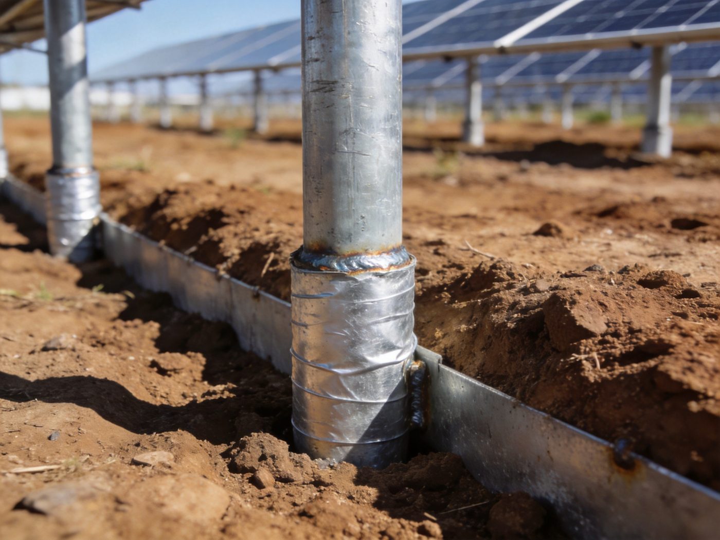
Corrosion protection is the engineering discipline that determines whether a solar foundation structural system performs to its designed 25–40 year service life or fails prematurely — and it is the most frequently underspecified element in solar foundation engineering precisely because corrosion damage develops slowly, invisibly, and is rarely detected until structural capacity has already been significantly compromised. Steel components in solar foundation systems — piles, ground screws, anchor bolts, rock anchor rods, and concrete reinforcement — are embedded in soil and exposed to atmospheric conditions that create a persistent electrochemical corrosion environment; without specification of the correct protection class matched to the site-specific soil aggressiveness and atmospheric corrosion category, metallic foundation elements experience progressive cross-section reduction that reduces structural capacity over time, eventually creating a gap between the designed-in safety factor and the actual safety factor remaining at the section’s corroded state. A pile or screw that provides FS = 2.5 against wind uplift at installation provides FS = 1.2 after 25 years of unprotected corrosion in Class C4 (marine) soil — below the minimum acceptable safety factor for a permanent structure — while a correctly protected equivalent element provides FS = 2.3 at year 25. For a complete overview of all solar foundation types and their structural design requirements, visit our Solar Foundation Systems Guide.
The corrosion protection specification for solar foundations is a two-environment problem: (1) below-grade soil corrosion, governed by soil electrochemical properties (resistivity, pH, sulfate content, chloride content, moisture content, and redox potential); and (2) above-grade atmospheric corrosion, governed by the environmental corrosion category (C1–C5 per ISO 9223) at the project location. Both environments must be characterized independently and the more aggressive of the two protection classes governs the specification for the portion of the foundation element in that zone — a project in a mild inland climate may have C2 atmospheric exposure but C4 soil corrosion from naturally occurring aggressive clay chemistry, requiring high-specification below-grade protection even in an apparently benign climate. The engineering process of characterizing both environments, assigning corrosion protection classes, specifying the correct protection system for each foundation type and zone, and verifying protection quality during installation is the complete corrosion protection engineering workflow that determines solar foundation 30-year durability.
Technical Snapshot: Corrosion Protection Parameters for Solar Foundation Engineering
| Parameter | Classification / Typical Range | Governing Protection Decision | Engineering Note |
|---|---|---|---|
| Atmospheric Corrosion Category (ISO 9223) | C1 (very low: indoor, dry); C2 (low: rural inland, low humidity); C3 (medium: urban/industrial inland, moderate humidity); C4 (high: industrial coastal, marine splash zone); C5 (very high: permanent marine immersion, industrial with high salinity) | Above-grade coating system and galvanization thickness for all metallic foundation elements above ground surface; zinc consumption rate and coating lifespan prediction | ISO 9223 corrosion categories are defined by annual mass loss of zinc reference specimens: C1 <0.7 g/m²/yr; C2 0.7–5 g/m²/yr; C3 5–15 g/m²/yr; C4 15–30 g/m²/yr; C5 >30 g/m²/yr; C5 coastal sites consume HDG zinc at 5–10× the rate of C2 rural inland sites — reducing 85 µm HDG coating life from 60–80 years (C2) to 8–15 years (C5) and requiring duplex or stainless specification for 25-year design life compliance |
| Soil Resistivity (ρ, Ω·cm) | ρ > 10,000 Ω·cm: non-corrosive (Class I); ρ 5,000–10,000: mildly corrosive (Class II); ρ 2,000–5,000: moderately corrosive (Class III); ρ 1,000–2,000: highly corrosive (Class IV); ρ <1,000 Ω·cm: extremely corrosive (Class V) | Soil corrosion class determination; below-grade protection system selection; corrosion allowance thickness in structural capacity calculations | Soil resistivity is the single most important soil corrosion parameter — low resistivity enables rapid ion mobility through the electrolyte (soil moisture), accelerating the electrochemical corrosion cell; wet, fine-grained soils with high ionic content (clay, marine silt, organic soil) have ρ = 200–2,000 Ω·cm; dry sandy soils have ρ = 5,000–50,000 Ω·cm; resistivity must be measured at field moisture content (ASTM G57 four-electrode Wenner method), not at dried sample — drying increases ρ by 5–50× and completely misrepresents field corrosion aggressiveness |
| Soil pH | pH < 4.0: extremely aggressive (acid sulfate soils, peat); pH 4.0–5.5: highly aggressive; pH 5.5–6.5: moderately aggressive; pH 6.5–8.5: non-aggressive (neutral, near-neutral); pH > 8.5: mildly aggressive alkaline (high pH inhibits most corrosion but can accelerate cathodic disbondment of organic coatings) | Steel corrosion rate amplification factor; zinc coating stability (zinc dissolves rapidly below pH 6 and above pH 12); stainless steel alloy selection in acid soil | Acid sulfate soils (coastal reclaimed land, tropical mangrove soils, some agricultural land with drained pyritic material) can reach pH 2.5–4.0 — highly aggressive to both steel and zinc coatings; HDG zinc dissolves rapidly below pH 6 (zinc amphoteric behavior — soluble in both strong acid and strong alkali); acid sulfate soil sites require stainless steel (316L minimum) for all below-grade metallic foundation elements or cathodic protection supplementing any metallic protection system; acid sulfate soil identification from pH, sulfide content, and soil color (pale yellow jarosite mineral) in the geotechnical investigation |
| Chloride Content (Cl⁻, mg/kg soil) | Cl⁻ < 50 mg/kg: non-aggressive; Cl⁻ 50–200 mg/kg: mildly aggressive; Cl⁻ 200–1,000 mg/kg: moderately aggressive; Cl⁻ > 1,000 mg/kg: highly aggressive (typical for coastal marine soils within 500 m of salt water) | Galvanic zinc consumption rate amplification; stainless steel alloy selection (304 vs 316L — critical distinction in chloride environments); concrete reinforcement protection class (epoxy-coated or stainless rebar for Cl⁻ > 500 mg/kg) | Chloride ions are the most aggressive corrosion accelerants for steel and zinc in soil: Cl⁻ disrupts the passive oxide film on stainless steel (pitting corrosion initiation at Cl⁻ > critical pitting concentration — 316L pitting resistance equivalent PREN > 24 required for Cl⁻ > 500 mg/kg; duplex stainless 2205 PREN > 35 for Cl⁻ > 1,000 mg/kg); Cl⁻ directly replaces protective zinc carbonate (ZnCO₃) passivation layer on HDG zinc with soluble ZnCl₂ — rapidly consuming the zinc coating; in aggressive coastal soil, HDG zinc consumption rates of 20–50 µm/yr are observed, consuming a 100 µm HDG coating in 2–5 years without supplemental protection |
| Sulfate Content (SO₄²⁻, mg/kg soil) | SO₄²⁻ < 500 mg/kg: non-aggressive to concrete; SO₄²⁻ 500–3,000: moderately aggressive (Class 1 per ACI 318-19); SO₄²⁻ 3,000–10,000: highly aggressive (Class 2); SO₄²⁻ > 10,000 mg/kg: very highly aggressive (Class 3) | Concrete foundation sulfate resistance class (Type II or V Portland cement; SCM supplementation); steel corrosion rate (sulfate-reducing bacteria in anaerobic high-sulfate soil produce H₂S that dramatically accelerates steel corrosion) | Sulfate-reducing bacteria (SRB) in anaerobic (oxygen-depleted) high-sulfate soil — common below the water table in organic-rich clay or near industrial contamination — produce hydrogen sulfide (H₂S) as a metabolic byproduct; H₂S accelerates steel corrosion at rates 3–10× higher than abiotic corrosion at equivalent soil conditions; MIC (microbiologically influenced corrosion) from SRB is detected from redox potential Eh measurement (< −200 mV indicates anaerobic SRB-active conditions) and sulfate concentration; foundations in MIC-active soil require cathodic protection supplementing HDG coating |
| Hot-Dip Galvanization (HDG) Thickness (µm) | ASTM A123 minimum: 45–85 µm depending on steel thickness category; EN ISO 1461 minimum: 45–85 µm; Heavy-duty solar specification: 85–100 µm average; Duplex system (HDG + powder coat): 85 µm zinc + 60–80 µm organic topcoat | Below-grade and above-grade protection life prediction; corrosion allowance remaining at end of design life; coating specification in project procurement documents | HDG coating life prediction from ISO 14713-1: L = Tzinc/Cr where Tzinc = zinc coating thickness (µm) and Cr = zinc corrosion rate (µm/year) for the applicable ISO 9223 corrosion category; for 85 µm HDG at C3 (5–15 µm/yr, use 10 µm/yr mid-range): L = 85/10 = 8.5 years to first corrosion of substrate — requiring duplex or thicker specification for 25-year design life; in C2 (0.7–5 µm/yr, use 2.5 µm/yr mid-range): L = 85/2.5 = 34 years — meets 25-year design life; the coating life calculation must be performed for the actual site ISO corrosion category, not for a generic or conservative assumption |
| Corrosion Allowance (CA, mm) | Class I soil (non-corrosive): CA = 0 mm (protected surface assumed adequate); Class II (mildly corrosive): CA = 0.5–1.0 mm over 25 years; Class III (moderately corrosive): CA = 1.0–1.5 mm; Class IV (highly corrosive): CA = 1.5–2.5 mm; Class V (extremely corrosive): CA = 2.5–4.0 mm (or cathodic protection + standard protection) | Structural capacity calculation at end of design life: effective section area Anet = Agross − CA × perimeter; bending capacity Mn,25yr = Fy × Snet; confirmed ≥ design demand with FS ≥ 1.5 at end of life | Corrosion allowance is added to the structurally required wall thickness to ensure that after 25 years of corrosion, the remaining section still has adequate structural capacity; for a 4 mm wall thickness 76 mm tube screw in Class IV soil (CA = 2.0 mm): effective wall at year 25 = 4.0 − 2.0 = 2.0 mm — 50% of original wall; section modulus reduction = approximately 55% for a thin-walled tube; bending capacity at year 25 = 45% of original design value; if original FS = 2.5 against wind bending, year-25 FS = 2.5 × 0.45 = 1.13 — below the minimum acceptable FS; solution: increase wall thickness to 6 mm or specify HDG + epoxy duplex system to reduce effective corrosion rate to CA = 0.5 mm equivalent |
Why Corrosion Protection Matters in Solar Foundation Engineering
Environmental Exposure Risks: Soil, Moisture, Chloride, and Industrial Atmosphere
Solar foundation elements face a uniquely challenging corrosion environment because they span multiple exposure zones simultaneously — the above-grade shaft section in the atmospheric zone, the ground surface zone (the most aggressively corrosive location due to alternating wet-dry cycling with maximum oxygen availability), and the below-grade embedded section in the soil electrochemical zone. Each zone has distinct corrosion drivers: (1) Atmospheric zone: UV radiation, temperature cycling, humidity variation, and atmospheric pollutant deposition (SO₂ in industrial zones, NaCl in coastal zones) degrade organic coatings and consume zinc on HDG surfaces at rates governed by the ISO 9223 corrosion category; C5 coastal industrial sites within 500 m of the ocean experience annual zinc consumption of 25–40 µm/year — depleting an 85 µm HDG coating in 2–3 years; (2) Ground surface zone (splash and condensation zone, ±300 mm from surface): this is consistently the most corrosive location for any vertically embedded foundation element — it combines the soil electrochemical conditions from below with atmospheric oxygen availability from above, creating optimal conditions for differential aeration cells (the most energetic corrosion mechanism); pitting corrosion rates at the ground surface zone are typically 3–8× higher than either the purely atmospheric or purely buried sections; all corrosion protection specifications for solar foundations must explicitly address the ground surface zone with the highest protection level specified; (3) Below-grade soil zone: corrosion driven by soil resistivity, pH, chloride, sulfate, moisture content, and the presence of sulfate-reducing bacteria in anaerobic zones; soil corrosion aggressiveness varies from non-corrosive (dry sandy soil, ρ > 10,000 Ω·cm) to extremely corrosive (marine clay, ρ = 200–500 Ω·cm, Cl⁻ > 1,000 mg/kg) — a 50× variation in corrosion aggressiveness that requires correspondingly different protection specifications.
Structural Integrity Over Time: Corrosion as a Capacity Reduction Mechanism
Corrosion reduces solar foundation structural capacity through three simultaneous degradation pathways, all of which act progressively over the project life: (1) Wall thickness reduction: uniform corrosion removes metal from the outer surface of tubular or plate sections, reducing the net cross-sectional area available for axial force, shear, and bending moment resistance; for a 76 mm outer diameter × 4 mm wall tube screw losing 0.08 mm/year from the outer surface in Class III soil: after 25 years the wall is 4.0 − (0.08 × 25) = 2.0 mm — reducing the plastic section modulus Z by approximately 50% and the bending capacity Mp = Fy × Z by 50%; (2) Pitting corrosion stress concentration: localized pitting creates geometric discontinuities in the shaft surface — pit depths of 1–3 mm in a 4 mm wall section create stress concentration factors kt = 2–5 at pit tips; under cyclic wind loading (10⁶–10⁷ cycles over 25 years), these stress concentrations initiate fatigue cracks at applied stresses well below the static yield strength, potentially producing fatigue fracture at 30–60% of the nominal yield stress; (3) Connection zone degradation: bolt holes, thread roots, and weld zones experience preferential corrosion at 2–5× the shaft surface rate due to residual stress concentration and metallurgical inhomogeneity at these locations; connection zone pitting in anchor bolt threads reduces the effective thread engagement length and the tensile proof load — the connection fails before the shaft fails, typically without visible external evidence of the degradation. Understanding how corrosion-induced section loss translates to reduced load transfer capacity — and the structural safety factor implications over the design life — is developed in the load transfer principles resource.
Economic Impact of Corrosion Failure: Remediation vs Prevention Cost Analysis
Corrosion failure in solar foundations is an economically catastrophic event relative to the cost of preventing it through correct initial protection specification. The cost comparison: specifying 85 µm HDG instead of 45 µm HDG on a ground screw adds $3–$8 per screw in material cost; specifying duplex (HDG + powder coat) adds $12–$22 per screw; specifying 316L stainless steel at the anchor head connection instead of carbon steel adds $8–$15 per connection. At a 5,000-screw 20 MWp project: upgrading from 45 µm to 85 µm HDG = $15,000–$40,000 total incremental cost. The remediation cost for corrosion-related foundation failure on the same project — requiring screw extraction (if extractable after corrosion), replacement installation, structural realignment, and electrical re-commissioning — ranges from $1,500–$4,500 per affected foundation position; if 20% of foundations fail corrosion-induced structural capacity check at year 15 (1,000 positions): remediation cost = $1,500,000–$4,500,000 — a 37–112× cost ratio relative to the initial protection upgrade. Beyond direct remediation cost: a corrosion-related foundation structural failure that causes module damage activates the module warranty void (most module manufacturers void warranties for structural installation failures), insurance claims, and potential regulatory compliance issues in jurisdictions with solar safety inspection requirements.

Video: galvanized steel solar mounting system.
Corrosion Mechanisms in Steel Solar Foundation Elements
Electrochemical Corrosion Process: The Fundamental Mechanism
All corrosion of metallic solar foundation elements is fundamentally electrochemical — it requires the simultaneous presence of an anode (metal oxidation site), a cathode (oxygen reduction site), an electrolyte (ion-conducting medium, typically soil moisture), and an electrical conductor connecting anode and cathode (the metal itself). The four-component corrosion cell is thermodynamically spontaneous for steel (iron) in contact with oxygenated water: at the anode Fe → Fe²⁺ + 2e⁻ (metal dissolves); at the cathode O₂ + 2H₂O + 4e⁻ → 4OH⁻ (oxygen reduced); ions migrate through the electrolyte (soil moisture); electrons migrate through the metal from anode to cathode; Fe²⁺ + 2OH⁻ → Fe(OH)₂ → further oxidation to Fe(OH)₃ → dehydration to Fe₂O₃ · H₂O (rust) — the visible corrosion product. Three types of corrosion cells are relevant to solar foundations: (1) Differential aeration cell (most important for solar foundations): forms where oxygen concentration differs along the foundation length — the above-grade shaft in oxygenated air is the cathode (high O₂ = reduction site); the buried shaft in oxygen-depleted soil is the anode (low O₂ = oxidation site); the metal shaft provides the electrical connection; this cell type is responsible for the characteristically higher corrosion at the ground surface zone where the oxygen differential is steepest; (2) Concentration cell: forms in variable soil profiles where ionic concentration differs between adjacent soil layers — the shaft portion in dilute-ion soil (high ρ, sandy layer) is the cathode; the shaft in concentrated-ion soil (low ρ, clay layer) is the anode; (3) Galvanic cell: forms when two dissimilar metals are in electrical contact in the presence of an electrolyte — the more active (anodic) metal corrodes preferentially; this is the basis of galvanic protection (zinc as sacrificial anode protecting steel) and galvanic attack (copper or stainless steel in contact with carbon steel — the carbon steel corrodes at accelerated rate).
Soil Corrosivity & pH Influence: The Electrochemical Environment
Soil corrosivity is characterized by five measurable parameters that together define the electrochemical aggressiveness of the soil environment: (1) Resistivity (ρ): the inverse of ionic conductivity — low ρ means high ion mobility in the electrolyte, enabling rapid charge transfer in the corrosion cell and high corrosion current density; ρ is the primary parameter for soil corrosion class assignment per AWWA C105, DIN 50929-3, and PTI DC80.3; (2) pH: determines the stability of protective oxide and hydroxide layers on steel and zinc surfaces; below pH 6: zinc passivation layer (Zn(OH)₂, ZnCO₃) dissolves rapidly and HDG protection is lost; below pH 4: direct steel dissolution accelerates (high H⁺ activity drives cathodic hydrogen evolution rather than oxygen reduction, maintaining high corrosion current even in low-oxygen environments); (3) Moisture content: soil moisture is the electrolyte — dry soil has high ρ (poor electrolyte) and minimal corrosion; saturated soil has minimum ρ and maximum corrosion rate; cyclic wet-dry conditions (most common in solar project soils) produce highest corrosion rates due to concentration of ions during drying cycles and re-dissolution during wetting; (4) Redox potential (Eh): Eh < −200 mV indicates anaerobic (oxygen-depleted) conditions — a marker for sulfate-reducing bacteria (SRB) activity and microbiologically influenced corrosion (MIC); these conditions occur below the water table in organic-rich soils and require corrosion protection beyond what standard electrochemical corrosion models predict; (5) Soil texture and structure: stiff clay creates differential stress on pile/screw shaft coatings during seasonal volume change (swelling in wet, shrinking in dry) — mechanically damaging the coating and creating bare metal zones that become preferential corrosion initiation sites.
Chloride-Induced Corrosion: The Dominant Aggressive Agent in Coastal and Marine Environments
Chloride ions (Cl⁻) are the most damaging corrosion accelerant for solar foundation steel because they attack the protective mechanisms of both carbon steel and stainless steel through distinct pathways: (1) Zinc coating attack: Cl⁻ replaces the stable zinc carbonate passivation layer (ZnCO₃) formed on HDG zinc in non-chloride environments with soluble zinc chloride (ZnCl₂) — which washes away in rain rather than forming a protective barrier; this eliminates the self-passivating property of zinc in chloride environments, converting HDG protection from a long-life passive barrier to a rapidly consumed sacrificial coating; in soil with Cl⁻ > 500 mg/kg or in C4/C5 atmospheric exposure from marine aerosol, HDG zinc consumption rates increase 3–8× relative to non-chloride conditions; (2) Passive film disruption on stainless steel: stainless steel relies on a thin Cr₂O₃ passive film for its corrosion resistance; chloride ions attack this film at surface heterogeneities (inclusions, grain boundaries, surface scratches) when Cl⁻ concentration exceeds a critical pitting threshold that depends on the alloy pitting resistance equivalent PREN = %Cr + 3.3 × %Mo + 16 × %N; for 304 stainless (PREN ≈ 18): pitting initiates at Cl⁻ > 200 mg/kg soil; for 316L (PREN ≈ 24): Cl⁻ > 500 mg/kg; for duplex 2205 (PREN ≈ 35): Cl⁻ > 2,000 mg/kg — making alloy selection critical in high-chloride soil; (3) Concentration during evaporation: in above-grade sections of coastal foundation elements, capillary rise draws chloride-laden soil water up the shaft; evaporation at the shaft surface concentrates chloride deposits that create very high local Cl⁻ concentration — exceeding the pitting threshold of standard alloys even at moderate bulk soil Cl⁻.
Galvanic Corrosion in Mixed Metal Assemblies: Foundation Connection Risks
Solar foundation assemblies inherently involve multiple metals in electrical contact — carbon steel pile or screw shaft, hot-dip galvanized (zinc) coating, stainless steel anchor bolts, aluminum mounting column adapters, and painted steel racking components — creating a galvanic series hierarchy where the more active metal preferentially corrodes when in electrical contact with a more noble metal through a common electrolyte. Critical galvanic couples in solar foundation assemblies and their design responses: (1) Zinc (HDG) + carbon steel: zinc is anodic to steel (zinc sacrifices to protect steel) — this is the intended galvanic protection mechanism; the area ratio is critical: a small zinc anode connected to a large steel cathode depletes the zinc rapidly; ensure that the HDG coating covers all steel surface area to maintain a large zinc-to-steel area ratio; (2) Stainless steel + carbon steel or zinc: stainless steel is strongly cathodic to both carbon steel and zinc; a stainless steel anchor bolt in contact with a HDG-coated carbon steel pile shaft creates a galvanic cell that accelerates zinc consumption at the contact zone; mitigation: nylon or PTFE isolating washers at all stainless-to-carbon steel or stainless-to-HDG interfaces; (3) Aluminum + carbon steel (with water electrolyte): aluminum mounting column adapters in contact with carbon steel pile shaft above grade can create a galvanic cell when water bridges the interface; mitigation: epoxy-coated or powder-coated interface contact surface; (4) Copper grounding electrode + steel foundation: copper grounding conductors connected to steel foundation elements create the most severe galvanic couple (copper is noble, steel is active) — accelerating steel corrosion at the connection point; mitigation: use zinc-coated steel grounding straps instead of copper where they contact steel foundations, or provide electrical isolation at the copper-to-steel transition. The soil electrochemical characterization that identifies the electrolyte conductivity (resistivity) governing galvanic corrosion cell current is part of the comprehensive site investigation framework in the soil geotechnical considerations resource.
Common Corrosion Protection Methods for Solar Foundation Elements
Hot-Dip Galvanization (HDG): The Primary Protection Method
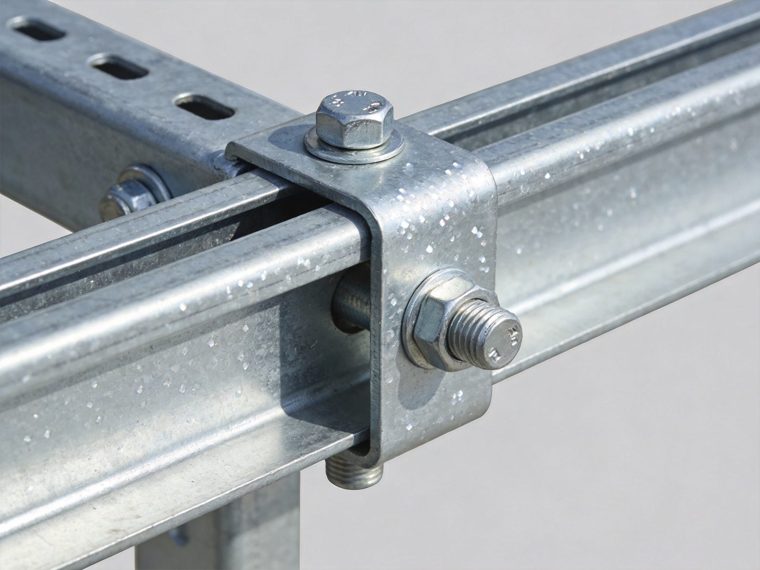
Hot-dip galvanization is the industry standard and most cost-effective corrosion protection method for carbon steel solar foundation elements — pile sections, ground screws, anchor bolts, and above-grade column adapters — providing both barrier protection (zinc coating isolates steel from the corrosive environment) and cathodic (galvanic) protection (zinc sacrificially corrodes to protect exposed steel at coating defects or cut edges). The HDG process: steel elements are cleaned by degreasing, pickling in hydrochloric acid, and fluxing before immersion in molten zinc at 450–460°C for 3–10 minutes; the zinc metallurgically bonds to the steel surface through a series of iron-zinc intermetallic compound layers (Γ, δ, ζ phases) with a pure zinc outer layer; the metallurgical bond cannot delaminate under mechanical loading or thermal cycling (unlike paint and powder coat adhesive bonds) — the primary advantage of HDG over organic coating systems. HDG specification standards: ASTM A123 (structural shapes and hardware, minimum 45–85 µm by steel thickness category); ASTM A153 (hardware items: bolts, nuts, washers, minimum 43–86 µm); EN ISO 1461 (European standard, equivalent thickness requirements); solar foundation procurement specifications should require 85 µm minimum average coating thickness (exceeding the ASTM A123 minimum for the thickest steel category) to maximize protection life across all site corrosion categories. Duplex protection system (HDG + organic topcoat): applying 60–80 µm powder coat or liquid epoxy paint over the HDG surface provides a synergistic protection enhancement — the organic topcoat provides barrier protection, eliminating the electrochemical driving force entirely while the HDG beneath acts as secondary protection at topcoat defects; duplex system total service life > 1.5× (HDG alone) + 1.5× (topcoat alone) due to the synergistic interaction; recommended for C4/C5 atmospheric environments and Class IV/V soil corrosion conditions.
Protective Coatings and Paint Systems: Secondary and Supplemental Protection
Organic protective coatings — epoxy paint, coal-tar epoxy, fusion-bonded epoxy (FBE), and polyurethane topcoat — provide barrier protection by isolating the steel surface from the electrolyte (soil moisture, atmospheric humidity). Coating systems for solar foundation below-grade protection: (1) Fusion-bonded epoxy (FBE): factory-applied electrostatic powder coating cured at 180–220°C; 300–600 µm dry film thickness; excellent adhesion, chemical resistance, and impact resistance; used as standalone below-grade protection for Class I/II soil or as the topcoat in duplex systems; cost: $8–$18/linear meter applied; (2) Coal-tar epoxy: two-component solvent-borne coating with coal-tar filler providing excellent water and chloride resistance; 300–500 µm DFT; effective in submerged, buried, and splash zone applications; historically used for pile below-grade protection; increasingly replaced by FBE and polyurethane systems in solar applications due to VOC content; (3) Polyurethane or polyurea spray coating: rapid-cure spray-applied coating, 1,500–3,000 µm DFT; excellent abrasion resistance for pile driving (withstands driving impact forces better than FBE); flexible enough to accommodate thermal cycling without cracking; recommended for driven pile below-grade applications in Class III/IV soil. Coating system specification requires: surface preparation to SA 2.5 (near-white blast, SSPC-SP10) before any coating application — coating applied over mill scale or surface rust provides near-zero adhesion life regardless of coating quality; dry film thickness verification per SSPC-PA2 (minimum 3 readings per 10 m² area, minimum individual reading ≥ 80% of specified DFT); adhesion test per ASTM D4541 (pull-off test, minimum 5 MPa for epoxy on blast-cleaned steel) on production test specimens from each batch.
Stainless Steel Components: The Premium Solution for Aggressive Environments
Stainless steel achieves corrosion resistance through the passive Cr₂O₃ film formed spontaneously on the surface in oxygenated conditions — providing intrinsic corrosion resistance without requiring a sacrificial coating or ongoing cathodic protection. Selection guide for solar foundation stainless steel specification: (1) AISI 304 / 1.4301 (18% Cr, 8% Ni, PREN ≈ 18): adequate for mild atmospheric (C2) and non-chloride soil environments (Cl⁻ < 200 mg/kg); most cost-effective stainless grade; used for anchor bolt sets in inland non-aggressive soils; (2) AISI 316L / 1.4404 (18% Cr, 10% Ni, 2% Mo, PREN ≈ 24): required for moderate chloride soil (Cl⁻ = 200–1,000 mg/kg) and C3/C4 atmospheric exposure; Mo addition improves pitting resistance; 316L (low carbon < 0.03%) prevents sensitization (carbide precipitation at weld heat-affected zones) in welded assemblies; the minimum specification for anchor head assemblies and connection hardware at coastal solar projects within 1,000 m of salt water; (3) Duplex stainless 2205 / 1.4462 (22% Cr, 5% Ni, 3% Mo, PREN ≈ 35): required for severe chloride soil (Cl⁻ > 1,000 mg/kg) and C5 marine environments; austenitic-ferritic microstructure provides 2× the yield strength of 316L, allowing smaller cross-sections at equivalent structural capacity; preferred for full stainless ground screws or rock anchor rods at highly aggressive coastal sites where HDG + duplex coating lifetime is insufficient for 25-year design life.
Cathodic Protection Systems: Active Electrochemical Defense
Cathodic protection (CP) converts the entire steel structure to a cathode by supplying external electrons — suppressing the anodic oxidation reaction at the steel surface and halting metal dissolution regardless of environmental aggressiveness. Two CP systems applicable to solar foundation elements: (1) Sacrificial anode CP: zinc or magnesium anodes (blocks or ribbon) electrically connected to the steel foundation elements; the anode metal dissolves preferentially, supplying electrons to keep the steel at cathodic potential; passive system — no external power required; suitable for isolated individual foundation elements in moderately corrosive soil; anode consumption rate and replacement schedule must be calculated for the design life; (2) Impressed current CP (ICCP): DC power supply connected between an inert anode bed and the steel foundations; current level adjusted to maintain steel potential at −850 mV vs Cu/CuSO₄ reference electrode (NACE standard criterion); active system requiring power supply, reference electrodes, monitoring, and periodic adjustment; suitable for large-scale protection of interconnected foundation arrays in Class IV/V soil or MIC-active (SRB) environments; CP is the only reliable protection method for foundations in acid sulfate soil (pH < 4) or SRB-active anaerobic soil where coating protection life is drastically reduced — CP supplements the coating to protect the inevitable coating defect zones.
Corrosion Considerations by Foundation Type
Pile Foundation Corrosion Protection: Zone-Stratified Specification
Driven steel pile foundations for solar mounting require a zone-stratified corrosion protection specification that addresses the three corrosion zones independently — atmospheric zone (above grade), ground surface splash zone (±300 mm), and below-grade zone — with different protection levels for each: (1) Atmospheric zone (above grade to column base): ISO 9223 corrosion category governs; C1/C2: HDG 85 µm; C3: HDG 85 µm + polyurethane topcoat; C4/C5: duplex HDG 85 µm + fluoropolymer or polyurethane topcoat 80 µm; (2) Ground surface splash zone (±300 mm from surface): always specified at one protection class higher than either the atmospheric or buried zone, as this is the most corrosive location; minimum: HDG 100 µm + 2× epoxy stripe coat at ground surface zone on all pile installations; for C4/C5 + Class III/IV soil: duplex HDG + polyurethane + additional barrier tape wrap at ground surface zone; (3) Below-grade zone: soil corrosion class (I–V from resistivity, pH, chloride, sulfate) governs; Class I: HDG 85 µm; Class II: HDG 85 µm + bituminous wrap or PE sleeve; Class III: FBE 400 µm or coal-tar epoxy 350 µm over blast-cleaned surface; Class IV/V: FBE 500 µm + CP supplementation or full stainless transition at ground zone. Pile driving applies significant impact and abrasion stress to the below-grade coating — coating systems for driven pile applications must be impact-resistant; FBE and polyurethane outperform coal-tar epoxy under driving impact; pile tip protection (sacrificial steel driving shoe or rock-point) prevents pile tip corrosion exposure during driving in hard soil. The complete driven pile structural design and installation specification integrating corrosion zone protection with pile section selection is in the pile driven systems resource.
Ground Screw Galvanization: The Helix Zone Critical Specification
Ground screws present a unique corrosion protection challenge: the helical installation process subjects the below-grade zinc coating to significant abrasion as the helix plates rotate through the soil, mechanically wearing the coating at the most critically loaded structural section — the helix bearing zone. Three ground screw-specific corrosion considerations: (1) Helix plate coating integrity after installation: laboratory studies of HDG ground screws recovered after installation in abrasive sandy soil show 20–60% zinc thickness reduction at helix plate leading edges versus the uninstalled coating thickness; this installation-induced coating loss is unavoidable and must be accounted in the effective protection specification — specifying 100 µm minimum HDG on screws intended for installation in sandy or gravelly soil provides post-installation zinc reserves equivalent to 85 µm on a non-abraded surface; (2) Thread root protection: screw threads are high-stress concentration zones and HDG zinc tends to be thinner at thread roots due to the geometry effect in the galvanizing process; thread roots in aggressive soil are the first locations to lose coating protection and initiate corrosion; factory thread-after-galvanizing (TAG) specification (threading the screw after HDG application) exposes bare steel at thread flanks and must be avoided; galvanize-after-threading (GAT) with zinc build-up at thread roots is the correct specification; (3) Galvanizing standard for screws: ASTM A153 governs hot-dip galvanizing of bolts and hardware items (which encompasses ground screws) — minimum 86 µm for items > 9.5 mm diameter; solar foundation specification should specify ASTM A153 Class C (85 µm minimum) with project-specific requirement for 100 µm minimum average for Class III/IV soil applications. The complete ground screw installation and specification document including corrosion zone protection requirements is in the ground screw foundations resource.
Concrete Foundation Anchor Bolt and Rebar Corrosion Protection
Concrete foundations present a layered corrosion protection structure: the concrete mass itself provides alkaline (pH 12–13) chemical protection to embedded carbon steel reinforcement through the passivation of the steel surface in the high-pH pore solution; this passive protection is reliable in non-aggressive soil but is progressively degraded by chloride ingress (pitting depassivation) and carbonation (CO₂ penetration reducing pH below the passive threshold of 9.5). Three corrosion protection requirements for concrete solar foundations: (1) Minimum concrete cover over reinforcement: cover provides the physical barrier length through which chloride and CO₂ must diffuse before reaching the steel; ACI 318-19 Table 20.6.1.3 minimum cover: 75 mm for concrete cast against and permanently exposed to earth (below grade); 50 mm for concrete exposed to earth or weather (above grade exposure); solar foundations in Class IV/V soil or C4/C5 atmosphere should specify 75 mm cover throughout regardless of ACI minimums, plus supplemental protection (epoxy-coated rebar or stainless rebar) when chloride risk is high; (2) Anchor bolt corrosion in the above-grade zone: anchor bolts projecting above the concrete surface are in the most aggressive zone (atmospheric + splash); HDG (ASTM A153, 86 µm minimum) is the minimum specification; C4/C5 sites or Class IV soil: 316L stainless anchor bolt sets with PTFE isolating washers at the aluminum column-to-anchor bolt interface; (3) Concrete mix design for chemical resistance: sulfate-resistant Type V cement or sulfate-resistant SCM supplementation (35–50% slag or 20–25% fly ash) for SO₄²⁻ > 1,000 mg/kg soil; low w/c ≤ 0.40 and minimum 28 MPa compressive strength reduces chloride diffusion coefficient by 3–5× relative to standard w/c = 0.50 mix — extending the time to chloride depassivation threshold from 10–15 years to 40+ years. The complete cold-climate and aggressive soil concrete foundation specification is in the concrete foundations resource.
Rock Anchor Head Protection: The Critical Above-Grade Exposure Zone
Rock anchor foundations concentrate corrosion risk at the above-grade anchor head assembly — the bearing plate, nut, anchor rod extension, and grout cap that terminate at the rock surface. Below the rock surface, the anchor rod in the grout-filled borehole is protected by the alkaline grout environment (pH 12–13, equivalent to concrete) against most corrosion mechanisms. The above-grade anchor head zone requires specific protection addressing three failure modes: (1) Crevice corrosion at bearing plate–rock interface: water infiltrating the gap between the bearing plate and the rock surface creates a crevice corrosion cell (low oxygen in the crevice = anodic zone; surrounding exposed metal = cathodic zone); the anodic dissolution rate in the crevice is 5–10× higher than on open surfaces; prevention: continuous bead of polyurethane sealant around the bearing plate perimeter applied after anchor rod tensioning, permanently sealing the plate-to-rock interface against water infiltration; (2) Anchor rod above-grade section in marine/industrial atmosphere: the anchor rod stub projecting above the bearing plate is exposed to C4/C5 atmospheric corrosion at the highest corrosion rate location in the foundation system; protection: 316L stainless for C3+ atmospheres; hot-dip galvanized with epoxy cap seal for C2/C3; the galvanized and epoxy-coated nut and cap assembly must be removable for anchor head inspection without damaging the protection system; (3) Grout cap integrity: the cementitious grout cap covering the anchor head nut must be free of cracks and completely seal the anchor head from moisture access; crack initiation in the grout cap from freeze-thaw cycling (alpine sites) or thermal cycling allows moisture access to the nut and rod interface — initiating galvanic and crevice corrosion at the least-accessible location in the assembly; epoxy grout cap or polymer-modified cement grout with crack resistance specification is required for cold-climate rock anchor applications. The complete rock anchor head protection specification and alpine environment durability requirements are in the rock anchoring systems resource.
Climate & Frost Impact on Corrosion Protection
Freeze-Thaw Cycling and Protective Coating Mechanical Damage
Freeze-thaw cycling in cold-region solar installations creates mechanical stress on corrosion protection coatings that is distinct from and additive to the electrochemical degradation mechanisms in non-cold climates. Three freeze-thaw coating damage mechanisms: (1) Coating delamination from substrate thermal cycling: the thermal expansion coefficient mismatch between zinc (αZn = 30.2 × 10⁻⁶/°C), organic coatings (αepoxy = 50–80 × 10⁻⁶/°C), and steel (αsteel = 12 × 10⁻⁶/°C) induces shear stress at the coating–steel interface during temperature cycling; over 50–150 freeze-thaw cycles per year (typical for continental cold climates), accumulated interface fatigue initiates microscopic delamination starting at coating edges, holes, and weld zones — creating pathways for moisture and electrolyte to reach the steel substrate; HDG (metallurgical bond) is immune to this mechanism; organic coatings over HDG (duplex system) are partially vulnerable but the HDG layer provides secondary protection when the organic topcoat delaminates; (2) Ice formation in soil-coating interface voids: micro-voids in the coating at the ground surface zone trap moisture; when this moisture freezes, it expands (9% volume) within the void, mechanically prying the coating from the substrate — similar to freeze-thaw damage in porous concrete; this is the primary mechanism for blistering and flaking of below-grade organic coatings in cold-climate soil; specification response: specify coatings with adhesion strength ≥ 7 MPa (ASTM D4541) and impact resistance ≥ 80 kg·cm (ASTM G14) for below-grade applications in cold climates; (3) De-icing salt contamination: solar projects on agricultural land or near roads where de-icing salt (NaCl, CaCl₂) is applied create a salt-contaminated ground surface environment equivalent to C4 coastal atmospheric conditions — dramatically accelerating zinc consumption at the above-grade shaft sections; projects in de-icing salt zones should be classified at C4 atmospheric exposure regardless of their geographic distance from the coast. The interaction between frost protection engineering (embedment depth requirements) and corrosion protection (coating system specification in the frost zone) is addressed in the frost protection design resource.
Coastal and High-Humidity Environments: Maximum Corrosion Aggressiveness
Coastal solar installations — projects within 1,000 m of salt water, where NaCl-laden marine aerosol deposits on all exposed surfaces — operate in C4/C5 atmospheric corrosion conditions that are the most demanding corrosion protection design scenario outside industrial chemical environments. Four design requirements specific to coastal solar foundations: (1) Marine aerosol deposition rate: salt deposition rate at C5 marine sites (within 200 m of salt water) reaches 300–1,500 mg Cl⁻/m²/day — equivalent to direct seawater spray; zinc consumption rate at C5: 25–40 µm/year; 85 µm HDG coating life: 2–3 years; duplex system (85 µm HDG + 80 µm polyurethane) life: 8–12 years; 316L stainless: > 25 years (with annual inspection); protection hierarchy for C5 coast: duplex + 316L connection hardware is the minimum for 25-year design life; (2) Chloride gradient with distance from shore: salt deposition rate decreases approximately as the inverse square of distance from the shore; at 200 m: C5; at 500 m: C4; at 1,000–1,500 m: C3; protection specification should be graduated with distance zones across the project footprint if the site spans the C3/C4/C5 boundary; (3) Regular fresh-water washing program: salt accumulation on above-grade coating surfaces can be reduced by fresh water washing (minimum 0.2 MPa, no detergent) at 3–6 month intervals, reducing effective chloride deposition to 30–50% of unwashed exposure; washing program specification is a valid engineering measure to reduce protection class requirement from C5 to C4-equivalent, allowing duplex HDG specification instead of full stainless at moderate additional O&M cost; (4) Design-life coating inspection and maintenance schedule: offshore-based corrosion inspection at 5-year intervals with zinc thickness measurement (ASTM E376 magnetic thickness gauge on HDG surfaces), adhesion test (ASTM D4541 spot pull-off at 5 locations per foundation per zone), and photographic documentation; action threshold: replace topcoat when measured DFT falls below 50% of original specification; replace HDG + topcoat when zinc thickness below 25 µm at ground surface zone.
Corrosion Protection vs Lifecycle Cost: The Engineering Economics
The lifecycle cost of corrosion protection in solar foundations is the total present value of: initial protection system cost (material + application) + periodic inspection and maintenance cost + remediation or replacement cost at end of protection system life — compared across protection system options for a 25-year project life. This analysis consistently demonstrates that the highest-specification initial protection system provides the lowest total lifecycle cost in all but the mildest corrosion environments.
| Protection System | Initial Cost per Screw/Pile (material) | Inspection Frequency | Expected Replacement Cost at Year 15–20 | Total 25-yr Lifecycle Cost per Element | Recommended Environment |
|---|---|---|---|---|---|
| HDG 45 µm (ASTM A123 minimum) | Base cost (0% premium) | Annual zinc thickness check at ground zone | $800–$1,500/position (corrosion remediation or screw replacement at year 10–15 in C3+ or Class III+ soil) | High (remediation cost dominates) | C1/C2 atmospheric + Class I/II soil only; not adequate for any moderate-aggressive exposure |
| HDG 85 µm (heavy-duty specification) | +8–15% vs 45 µm baseline | 5-year zinc thickness check at ground zone | No replacement required in C2/Class II; $400–$900/position in C3/Class III at year 20 | Low-medium (lowest 25-yr cost for C2/Class II) | C2/C3 atmospheric + Class I/II/III soil; standard solar foundation specification for inland sites |
| Duplex: HDG 85 µm + powder coat 80 µm | +25–40% vs 45 µm baseline | 5-year topcoat DFT + adhesion check | Topcoat touch-up at year 15 ($50–$120/position); no zinc replacement required in 25 years | Medium (optimum for C3/C4 + Class III/IV) | C3/C4 atmospheric + Class III/IV soil; coastal areas 500–2,000 m from salt water; industrial atmosphere |
| 316L Stainless steel (full below-grade) | +180–320% vs 45 µm baseline | Annual anchor head visual inspection only | No replacement required for 25+ year design life in any soil condition | High initial, near-zero lifecycle (optimum for C5/Class V) | C5 marine + Class IV/V soil; acid sulfate soil (pH < 5); SRB-active anaerobic soil; <200 m from salt water |
| HDG + Cathodic Protection | HDG cost + $3–$8/position for anode material | Annual anode inspection; replacement at 8–12 year intervals ($15–$40/position) | No steel remediation if CP maintained; anode replacement is the ongoing cost | Medium (optimum for Class IV/V MIC-active or acid soil with distributed foundation arrays) | Anaerobic/SRB-active soil (Eh < −200 mV); acid sulfate soil; interconnected large foundation arrays where ICCP is feasible |
The lifecycle cost analysis confirms that duplex protection (HDG + powder coat) is the economically optimal specification for the majority of utility-scale solar ground-mount projects at C3/C4 atmospheric exposure and Class III/IV soil — its 25–40% higher initial cost is recovered in full within 3–5 years from eliminated inspection, maintenance, and remediation expenditure. For the comprehensive cross-foundation-type lifecycle cost analysis that integrates corrosion protection cost with all other foundation cost components — including material, installation, testing, and 25-year maintenance — refer to the foundation cost comparison resource.
Corrosion Protection Requirements by Foundation Type
| Foundation Type | Primary Corrosion Risk Zone | Governing Corrosion Mechanism | Minimum Protection (Standard Site) | Upgraded Protection (Aggressive Site) | Risk Level Without Adequate Protection |
|---|---|---|---|---|---|
| Driven Pile (H-pile / pipe) | Ground surface zone (±300 mm); above-grade atmospheric zone in C4/C5 | Differential aeration cell at ground surface; atmospheric zinc consumption above grade; impact abrasion of below-grade coating during driving | HDG 85 µm + 2× epoxy stripe at ground zone; FBE 400 µm below grade for Class II/III soil | Duplex HDG + PU topcoat above grade; FBE 500 µm + CP system below grade for Class IV/V; 316L transition at ground zone for C4/C5 | Medium — large shaft area provides mass to sustain section loss before structural failure; but weld zone at pile extension joints is a critical corrosion concentration point that can fail before general section loss predicts |
| Ground Screw (Helical) | Helix plate bearing zone (installation abrasion); ground surface zone; shaft in corrosive soil | Installation abrasion of helix coating in sandy/gravelly soil; differential aeration at ground zone; pitting in chloride soil on thin post-installation zinc | HDG 100 µm (exceeding ASTM A153 minimum to compensate installation abrasion); galvanize-after-threading specification | Duplex HDG + epoxy topcoat for C3/C4 or Class III/IV; 316L full screw for C5/Class V or acid sulfate soil | Medium-High — helix zone is most critically loaded and most likely to have degraded coating post-installation; pitting in helix zone reduces bearing area and capacity; most common corrosion failure location in solar ground screws |
| Concrete Footing | Anchor bolts at above-grade interface; rebar in aggressive soil (Cl⁻ or SO₄²⁻); concrete surface above grade in freeze-thaw exposure | Anchor bolt atmospheric and crevice corrosion at column base interface; chloride ingress to rebar in marine/aggressive soil; concrete carbonation reducing rebar passive film pH | HDG anchor bolts (ASTM A153, 86 µm); minimum 75 mm concrete cover over rebar; air-entrained concrete (Class F2) above grade | 316L stainless anchor bolt sets for C4/C5 or Class IV/V; epoxy-coated or stainless rebar for Cl⁻ > 500 mg/kg soil; Type V sulfate-resistant cement for SO₄²⁻ > 1,000 mg/kg | Low (concrete bulk mass) to High (anchor bolt zone) — concrete provides excellent rebar protection in non-aggressive soil; anchor bolt failure from corrosion is the critical mode, occurring at the most highly stressed connection zone with least accessible protection |
| Ballasted System | Above-grade column and hardware in atmospheric zone only (no below-grade metallic element) | Atmospheric corrosion of above-grade column and connection hardware; no soil corrosion component | HDG 85 µm on all above-grade steel; standard powder-coat on aluminum column adapters | Duplex HDG + topcoat for C4/C5 coastal sites; 316L hardware in marine splash zone | Low — no buried metallic element means no differential aeration or soil corrosion; atmospheric corrosion is the only mechanism and is fully manageable with standard HDG specification in most environments |
| Rock Anchor | Above-grade anchor head assembly (bearing plate, nut, rod stub); grout-steel interface at grout cap crack locations | Crevice corrosion at bearing plate-rock interface; atmospheric corrosion of above-grade rod stub; grout cap cracking allowing moisture access to nut in freeze-thaw environments | HDG anchor head assembly; polyurethane bearing plate perimeter sealant; cementitious grout cap; 316L rod for C3+ atmosphere | Full 316L or duplex stainless anchor rod and head assembly for C4/C5 marine; epoxy resin grout cap for alpine freeze-thaw; additional anchor head enclosure (polycarbonate cap) for extreme marine spray | High at anchor head (critical zone with limited access for inspection and maintenance) — below-grade bond zone is protected by alkaline grout environment; anchor head is the vulnerable zone where failure initiates without visible warning |
The corrosion protection specification for each foundation type must be treated as a zone-specific engineering decision — not a single “protection class” applied uniformly to the entire element. The ground surface zone always requires the highest protection level regardless of the atmospheric and soil classification results. For the complete technical framework governing foundation selection across all structural, environmental, and commercial criteria — with corrosion protection as one of the engineering inputs to the integrated decision — refer to our complete solar foundation guide.
Corrosion Protection Engineering Design Checklist
- Soil corrosivity tested at the foundation installation depth: Soil resistivity measured per ASTM G57 (four-electrode Wenner method) at field moisture content — minimum 3 measurements per soil zone; pH measured per ASTM G51 on soil extract; chloride per ASTM D4327 or equivalent; sulfate per ASTM D516; redox potential Eh measured in situ (indicating anaerobic SRB-active conditions if Eh < −200 mV); corrosion class assigned per AWWA C105 or DIN 50929-3 using the lowest measured resistivity and most aggressive pH/Cl⁻/SO₄²⁻ result as governing values
- Atmospheric corrosion category confirmed from site location and industry/coastal proximity: ISO 9223 corrosion category assigned from: distance to coastline (<200 m: C5; 200–500 m: C4; 500–2,000 m: C3; >2,000 m: C2 or C3 depending on prevailing wind direction); proximity to industrial emission sources (SO₂, HCl); annual mean relative humidity and temperature (higher T + humidity = higher ISO corrosion rate); confirmed against NOAA National Acid Deposition Program data for SO₂ deposition at project location
- Coating thickness specified at the required level for the confirmed corrosion class: HDG thickness required: C1/C2 + Class I/II: 85 µm; C3 + Class II/III: 85 µm + ground zone stripe coat; C4 or Class III/IV: duplex 85 µm HDG + 80 µm topcoat; C5 or Class IV/V: duplex + CP or full stainless; coating specification written into procurement documents with ASTM/EN standard reference, minimum average and minimum individual measurement thicknesses, and inspection/acceptance requirements
- Corrosion allowance calculated and included in structural capacity verification at year 25: CA (mm/25 years) assigned per soil corrosion class; effective section modulus Snet,25yr = f(twall − CA); bending capacity Mn,25yr = Fy × Snet,25yr ≥ Mdesign/FS; if capacity does not meet FS requirement at year 25 with standard wall thickness: increase wall thickness, upgrade protection class, or add CP supplement to reduce effective corrosion rate; structural capacity with corrosion allowance documented in foundation engineering calculations
- Coastal exposure evaluated and xml protection class upgraded for salt deposition zones: Salt deposition rate from distance-to-coast mapping; if project spans multiple ISO zones (C3/C4 boundary within project footprint): zone-specific protection specifications with geographic boundary defined by GPS coordinates in the procurement document; de-icing salt application zones within 500 m of project boundary elevated to C4 equivalent regardless of geographic distance from coast; marine aerosol wind direction analysis confirming prevailing onshore wind exposure at the project site
- Drainage design confirmed to prevent persistent moisture accumulation at foundation head: Site grading slopes away from foundation positions (minimum 2% within 3 m); no ponding zones identified from topographic survey; subsurface drainage confirmed adequate to maintain groundwater below the splash zone depth; concrete footing tops sloped to drain at 3–5° from horizontal; anchor head drainage gap confirmed between bearing plate and rock surface at all rock anchor positions
- Inspection schedule defined and written into O&M documentation: Baseline inspection at project commissioning: HDG zinc thickness (ASTM E376 magnetic gauge), coating adhesion spot test (ASTM D4541), photographic documentation of all ground surface zones; periodic inspection schedule: C2/Class II: 10-year interval; C3/Class III: 5-year interval; C4/Class IV: 3-year interval; C5/Class V: annual; action thresholds documented: zinc < 40 µm at ground zone = immediate recoating; coating adhesion < 3 MPa = repair required; visible pitting depth > 1.5 mm = structural capacity reassessment required before next wind season
- Galvanic isolation confirmed at all dissimilar metal interfaces: Interface detail drawings reviewed for all stainless-to-HDG contacts (anchor bolt to pile shaft flange), aluminum-to-carbon steel contacts (column adapter to screw shaft), and copper grounding-to-steel contacts (grounding lug to pile shaft); PTFE or nylon isolating washers specified at all identified dissimilar metal interfaces; isolation resistance test on representative assembly samples (minimum 1 MΩ isolation resistance confirms effective galvanic isolation)
Failure Risks & Common Corrosion Design Mistakes
Underestimating Soil Corrosivity: The Most Consequential Design Error
The most frequently occurring and consequential corrosion design error in solar foundation engineering is specifying the protection system based on visual site description (“sandy soil, appears dry, no visible water”) or regional geological maps rather than site-specific measured soil electrochemical parameters. The failure mechanism: a solar project on agricultural land classified visually as “well-drained loamy soil” in a temperate inland climate is specified with standard 85 µm HDG on the assumption of Class I/II soil; post-installation laboratory testing of soil samples from the actual installation depth reveals pH = 4.8 (moderately aggressive), resistivity = 1,800 Ω·cm (Class IV — highly corrosive), and redox potential Eh = −280 mV (indicating SRB-active anaerobic conditions in the saturated subsoil below the seasonally dry surface) — a Class IV soil condition that requires HDG + FBE duplex or CP supplementation; the installed 85 µm HDG-only screws will lose effective coating protection within 5–8 years, requiring early remediation or structural capacity acceptance on reduced section at the most expensive phase of project life (when project finance debt is still outstanding). Prevention: soil corrosivity testing from geotechnical investigation samples is not optional — it is an engineering requirement for professional corrosion protection specification; the $3,000–$8,000 cost of soil chemistry testing on a 20 MWp project is less than the cost of remediating a single corrosion-compromised foundation cluster.
Inadequate Galvanization Thickness: Specifying to the Minimum Instead of the Design Life
ASTM A123 and ASTM A153 set minimum galvanization thicknesses for quality assurance purposes — they are the floor of acceptable manufacturing quality, not the engineering specification for a 25-year solar project design life in site-specific corrosion conditions. The error: procurement specifications that reference only “ASTM A123 compliant” without specifying a minimum thickness value in µm allow manufacturers to deliver 45–50 µm HDG product (meeting the ASTM A123 minimum for thinner steel categories) that provides inadequate protection life at C3 or higher atmospheric exposure. Engineering specification requirement: explicitly state minimum average coating thickness (85 µm for standard sites; 100 µm for screw helix plates; 120 µm for Class III/IV soil below-grade sections) in addition to ASTM A123 compliance — the project-specific minimum thickness requirements take precedence over the ASTM minimums when they are more stringent. Verification: independent third-party magnetic thickness gauge measurement (ASTM E376) on a 10% random sample of delivered foundation elements, with rejection and re-galvanizing required for any element below 80% of the specified minimum average — before any element is installed, as post-installation thickness measurement is impractical for below-grade sections.
Ignoring Coastal Conditions: The 10-Year Failure Pattern
Solar projects installed within 1,000–2,000 m of coastlines without C4/C5 atmospheric protection specification consistently show the same failure pattern: ground surface zone zinc coating visibly consumed (grey-white zinc corrosion products replaced by orange-red iron rust) within 3–5 years; first structural corrosion pitting in the ground surface zone shaft visible at 5–8 years; structural capacity assessment indicating FS < 1.5 at perimeter foundation positions at year 10–12; emergency remediation required before the project finance debt covenant period expires. The failure is entirely predictable from the ISO 9223 salt deposition rate at the site location — and entirely preventable by duplex or stainless specification at initial installation. The contributing factor: coastal solar projects are frequently developed by investors without in-house structural engineering expertise, relying on standard inland foundation specifications quoted by contractors without site-specific corrosion assessment; the corrosion risk is not visible at installation or in the first 2–3 years of operation, creating a false confidence in the standard HDG specification that is not challenged until visible rust appears.
Mixing Metals Without Galvanic Isolation: The Hidden Accelerated Corrosion Risk
Mixing stainless steel anchor bolts with carbon steel or HDG pile shaft flanges — a very common configuration in solar foundation column base assemblies — creates a galvanic cell that accelerates corrosion of the carbon steel or HDG element at the contact zone when moisture bridges the interface. The galvanic potential difference between 316L stainless (noble, cathodic) and carbon steel or zinc (active, anodic) is approximately 0.5–0.8 V — sufficient to drive significant galvanic corrosion current when the area ratio of cathode (stainless bolt) to anode (HDG pile flange around the bolt hole) is unfavorable. Quantification: a 316L M20 bolt in contact with a 5 mm × 5 mm zone of bare steel at the bolt hole edge (HDG coating worn by bolt installation torque) creates a cathode-to-anode area ratio of approximately 300:1 — concentrating the full galvanic current on the tiny bare steel area and producing corrosion rates 100–300× higher than the average zinc consumption rate on the same surface; visible pit formation at the bolt hole edge within 2–3 years at C3/C4 atmospheric exposure. Engineering specification: require PTFE washers or nylon isolating grommets at all stainless bolt-to-carbon steel or stainless bolt-to-HDG interfaces; confirm isolation resistance ≥ 1 MΩ on representative test assembly; specify stainless bolt hole sleeve where bolt passes through pile flange to prevent direct metal-to-metal contact.
Frequently Asked Questions
What is the difference between C3, C4, and C5 corrosion categories for solar foundations?
ISO 9223 corrosion categories C1–C5 quantify the aggressiveness of atmospheric corrosion environments based on the measured annual mass loss of zinc reference specimens exposed at the project location for 12 months under standard conditions. The practical distinction for solar foundation specification: C3 (medium) corresponds to urban and industrial inland environments with moderate humidity — annual zinc loss 5–15 g/m²/year; a standard 85 µm HDG coating (680 g/m² zinc) lasts approximately 45–136 years at C3 mid-range (10 g/m²/yr: 68 years) — meeting the 25-year design life comfortably with standard 85 µm HDG specification and no topcoat required. C4 (high) corresponds to industrial coastal environments, sites near chemical or petrochemical facilities, or sites within 500–2,000 m of the ocean — annual zinc loss 15–30 g/m²/year; 85 µm HDG lasts 23–57 years at C4 mid-range (22 g/m²/yr: 31 years) — borderline for 25-year design life, requiring duplex specification for reliable margin. C5 (very high) corresponds to marine splash zones within 200 m of salt water or permanent chemical industrial exposure — annual zinc loss >30 g/m²/year; 85 µm HDG lasts < 23 years at C5 minimum — falls within the 25-year design life, making standard HDG non-compliant; duplex system required at minimum, stainless preferred. The selection rule: confirm ISO category from nearest atmospheric exposure station or salt deposition measurement; specify HDG alone for C2; HDG for C3 with ground zone stripe coat; duplex for C4; duplex or stainless for C5.
How thick should the hot-dip galvanization be on solar ground screws?
The correct HDG thickness specification for solar ground screws depends on both the site corrosion class and the installation method’s effect on coating integrity. Three specification tiers: (1) Standard inland sites (C2/C3, Class I/II soil): 85 µm minimum average per ASTM A153 Class C (the heavy-hardware category for bolts and hardware > 9.5 mm diameter); individual measurements minimum 65 µm (80% of average); this is the minimum adequate specification for non-aggressive sites with 25-year design life; (2) Moderate aggressive sites (C3/C4, Class II/III soil, or any site with sandy/gravelly soil above the helix): 100 µm minimum average, 80 µm minimum individual, specified explicitly in procurement documents as exceeding the ASTM A153 minimum; the 100 µm specification compensates for 15–25 µm installation abrasion on helix plate leading edges in sandy soil, maintaining the equivalent of 85 µm effective post-installation thickness at the helix bearing zone; (3) Aggressive sites (C4/C5, Class III/IV soil, coastal, industrial): duplex specification — 100 µm HDG + 60–80 µm factory-applied powder coat epoxy or polyurethane; the organic topcoat provides the primary barrier at the ground surface zone where the combination of atmospheric and soil corrosion produces the highest attack rate. Verification: Wettability test of the galvanized surface before powder coat application (contact angle < 30° confirms adequate surface energy for coating adhesion); adhesion pull-off test per ASTM D4541 on representative specimens at 72 hours after powder coat application; rejection lot threshold: any individual zinc thickness reading < 65 µm at helix plate or shaft surface.
Does concrete protect rebar from corrosion in solar foundations?
Concrete provides reliable electrochemical protection to embedded carbon steel reinforcement through its naturally high alkalinity (pH 12–13 in fresh concrete pore solution) — the high OH⁻ concentration passivates the steel surface with a dense Cr₂O₃-like iron oxide film that suppresses corrosion to negligible rates. This passive protection is reliable and essentially maintenance-free for the 25-year project life in non-aggressive soil conditions (Cl⁻ < 200 mg/kg, SO₄²⁻ < 500 mg/kg, no carbonation threat). The passive protection is progressively lost under two mechanisms: (1) Chloride depassivation: Cl⁻ ions diffusing through the concrete cover reach the rebar surface and locally disrupt the passive film — initiating pitting corrosion when Cl⁻ exceeds the critical threshold (typically 0.3–0.6% Cl⁻ by weight of cement at the rebar depth); the time to depassivation is governed by Fick’s diffusion law: t = d²/(2D) where d = cover depth and D = chloride diffusion coefficient (3–12 × 10⁻¹² m²/s for standard concrete); at d = 75 mm and D = 5 × 10⁻¹² m²/s: t = (0.075)²/(2 × 5 × 10⁻¹²) = 562,500,000 seconds ≈ 17 years — marginally acceptable for a 25-year design life in C4 atmospheric exposure; increasing cover to 90 mm extends depassivation time to 25 years in the same conditions; (2) Carbonation: atmospheric CO₂ diffuses into the concrete and reacts with Ca(OH)₂ to form CaCO₃ — reducing pore solution pH from 12–13 to below 9.5 and eliminating the alkaline passivation of the rebar; carbonation front depth grows proportionally to √time; at d = 50 mm above grade with standard concrete (w/c = 0.50) in C3 atmosphere: carbonation front reaches rebar in approximately 30–40 years — adequate for 25-year design life with standard specification.
What is duplex coating and when is it required for solar foundations?
Duplex coating is the combination of hot-dip galvanization (HDG) as the base layer with an organic coating (powder coat, liquid epoxy, or polyurethane paint) applied over the HDG surface — creating a two-layer protection system that provides both barrier protection (organic topcoat) and cathodic/sacrificial protection (zinc layer) simultaneously. The critical performance advantage of duplex over either layer alone: (1) the organic topcoat prevents the electrochemical driving force from reaching the zinc surface, dramatically reducing zinc consumption rate to near zero while the topcoat is intact — effectively multiplying the HDG coating life by the organic topcoat barrier effectiveness factor (3–5× extension of HDG life under the topcoat); (2) when the organic topcoat is locally damaged (scratch, impact, installation damage), the exposed zinc provides sacrificial cathodic protection to the underlying steel — preventing rust initiation at the defect that would otherwise propagate laterally under the topcoat in a single-layer organic coating; the duplex combination life is 1.5× (HDG life alone) + 1.5× (topcoat life alone) due to this synergistic interaction per ISO 14713-1. Duplex specification triggers for solar foundations: ISO 9223 C4 or C5 atmospheric exposure; soil corrosion Class III or IV; sites within 500 m of salt water; industrial atmosphere with SO₂ or HCl emission sources within 2 km; sites with de-icing salt application within 500 m of project boundary; any site where HDG-only 25-year life calculation shows protection life margin < 5 years above the 25-year design life.
How does freeze-thaw cycling affect corrosion protection coating performance?
Freeze-thaw cycling degrades organic corrosion protection coatings through three distinct mechanical mechanisms that act cumulatively over the project life: (1) thermal expansion coefficient mismatch between coating and steel substrate generates cyclic shear stress at the coating-steel interface — at 100 freeze-thaw cycles/year: 2,500 fatigue cycles over 25 years; organic coatings with elongation capacity < 2% (rigid epoxy systems) develop interface delamination starting at geometric discontinuities (edges, bolt holes, weld zones) within 10–15 years; flexible polyurethane (elongation 100–400%) resists this mechanism far better than rigid epoxy and is the preferred topcoat for cold-climate solar foundations; (2) ice expansion in micro-voids at the coating-substrate interface mechanically pries the coating from the steel — requiring adhesion strength specifications ≥ 7 MPa (ASTM D4541) and surface preparation to SA 2.5 blast (profile 40–75 µm Rz) to minimize void formation; (3) cyclic formation and dissolution of salt deposits in the coating surface during freeze-thaw cycling in de-icing salt or marine environments locally concentrates Cl⁻ at pin-hole defects, creating aggressive localized corrosion micro-cells; HDG beneath the organic topcoat is immune to this mechanism (zinc does not have pin-hole defects), which is a key reason for specifying duplex rather than organic-only coatings in cold-climate solar projects.
What corrosion protection is needed for solar foundations in coastal areas?
Solar foundations within 2,000 m of the ocean require elevated corrosion protection specification that progresses with decreasing distance to the shore: (1) 2,000–1,000 m from shore (C3 coastal inland): 85 µm HDG + ground surface zone polyurethane stripe coat on above-grade shaft; 316L stainless anchor bolts at column base; regular fresh-water washing of above-grade surfaces at 6-month intervals; (2) 1,000–500 m from shore (C4 coastal): duplex specification — 85 µm HDG + 80 µm polyurethane topcoat on all above-grade sections; 316L stainless all connection hardware; PTFE isolation at all dissimilar metal contacts; 5-year inspection cycle with zinc thickness measurement; (3) 500–200 m from shore (C4/C5 high coastal): duplex specification + 316L stainless at all above-grade sections and all connection hardware; ICCP supplementation for below-grade sections in low-resistivity coastal soil; enhanced inspection at 3-year intervals; fresh-water washing at 3-month intervals; (4) <200 m from shore (C5 marine): 316L or duplex stainless (2205 for soil Cl⁻ > 1,000 mg/kg) for all metallic foundation elements above and below grade; sacrificial zinc anode cathodic protection on all below-grade elements; minimum 75 mm concrete cover on concrete elements; annual inspection and anode consumption measurement.
How do I determine the correct corrosion protection class for a solar project site?
Corrosion protection class determination for a solar project requires a parallel two-track investigation: above-grade atmospheric corrosion category (ISO 9223) and below-grade soil corrosion class (AWWA C105 or equivalent). Above-grade determination: (1) confirm project coordinates and distance to nearest coastline; (2) identify industrial emission sources within 2 km (SO₂, HCl); (3) confirm prevailing wind direction from nearest meteorological station; (4) assign ISO 9223 category from published atmospheric exposure station data, or from first-year zinc coupon exposure measurement; (5) adjust for de-icing salt application proximity. Below-grade determination: (1) collect soil samples from the planned foundation installation depth during geotechnical investigation (same mobilization as SPT borings or CPT — no additional mobilization cost); (2) measure resistivity (ASTM G57), pH (ASTM G51), chloride (ASTM D4327), sulfate (ASTM D516), and redox potential Eh (in-situ measurement in open borings); (3) classify per AWWA C105 using the most aggressive measured parameter value; (4) check for acid sulfate soil indicators (low pH, yellow jarosite, high sulfide). The governing protection specification uses the more aggressive of the atmospheric and soil classifications for each zone — a C2 atmospheric site with Class IV soil uses Class IV protection specification for the below-grade zone and C2 specification for the above-grade zone. The comprehensive soil chemistry testing program that generates these parameters as part of the standard geotechnical investigation is in the soil investigation report resource.
What is the expected lifespan of hot-dip galvanized solar foundation elements?
The expected lifespan of HDG solar foundation elements — defined as the time until the zinc coating is depleted to < 20 µm (the minimum thickness providing meaningful galvanic protection to the underlying steel) — is calculated from the ISO 9223 corrosion category and soil corrosion class specific zinc consumption rates per ISO 14713-1. Above-grade lifespan (atmospheric): at 85 µm HDG initial thickness, depleting to 20 µm residual = 65 µm consumed; C2 (2.5 µm/year mid-range): 65/2.5 = 26 years — borderline for 25-year design life; C3 (10 µm/year mid-range): 65/10 = 6.5 years — inadequate for 25-year design life without topcoat; C4 (22 µm/year mid-range): 65/22 = 3 years — grossly inadequate without duplex. Below-grade lifespan (soil): soil zinc consumption rates per ISO 9223 equivalent for soil: Class I (1–2 µm/year): 65/1.5 = 43 years; Class II (2–5 µm/year): 65/3.5 = 19 years — below 25-year target, requiring 100 µm+ HDG or duplex; Class III (5–10 µm/year): 65/7.5 = 8.7 years — requires duplex; Class IV (10–20 µm/year): 65/15 = 4.3 years — requires FBE + CP. These calculations confirm the central corrosion protection engineering conclusion: standard ASTM A123 minimum HDG (45–55 µm) provides < 25-year design life in any environment more aggressive than C2/Class I; project-specific 85–100 µm specification meets design life only in C2/C3 + Class I/II; duplex or stainless is required for reliable 25-year performance in C4+ or Class III+ environments.
Related Engineering Topics
- Wind load calculation — Wind loading and corrosion protection are linked through structural safety factor over time: the wind load calculation establishes the design demand on each foundation element; the corrosion protection specification determines whether the structural capacity supplying the required safety factor against that wind demand remains adequate over the full project life; a foundation with FS = 2.5 against design wind uplift at installation and corrosion-reduced FS = 1.1 at year 20 is structurally non-compliant not because the wind load changed but because the capacity degraded from inadequate corrosion protection — making corrosion protection engineering a direct extension of the structural wind load design process
- Seismic design — Seismic design for solar foundations in corrosive coastal and industrial environments (which frequently overlap with high-seismicity zones in Pacific Rim locations — California coast, Japan, New Zealand, Chile) must account for corrosion-reduced structural capacity in the seismic load combination; the Ω0-amplified seismic connection design force may exceed the corrosion-reduced anchor bolt tensile capacity at year 20 if the initial protection specification was inadequate for the site corrosion class; seismic zones with C4/C5 atmospheric exposure require explicit year-25 structural capacity verification in the seismic load combination, not just at installation
- Frost depth design — Cold-climate solar foundations face a combined frost-corrosion design challenge: freeze-thaw cycling mechanically damages organic corrosion protection coatings at the ground surface zone (the most critical corrosion location), while the increased moisture at the frost-active zone (seasonal saturation from snowmelt infiltration) elevates soil corrosion aggressiveness in the frost-critical depth range; the interaction requires that cold-climate solar foundation corrosion specifications explicitly address coating freeze-thaw resistance (polyurethane over rigid epoxy for flexibility) and specify the ground surface zone protection at the C4/Class IV level regardless of the bulk atmospheric and soil corrosion classifications
Prepare for project-specific review
Use this guide to organize the site, load, system and compliance inputs that a product supplier, licensed engineer, installer or local authority will need. PVRack does not provide project-specific engineering approval or supplier quotations.